• Which the release of FS2020 we see an explosition of activity on the forun and of course we are very happy to see this. But having all questions about FS2020 in one forum becomes a bit messy. So therefore we would like to ask you all to use the following guidelines when posting your questions:

    • Tag FS2020 specific questions with the MSFS2020 tag.
    • Questions about making 3D assets can be posted in the 3D asset design forum. Either post them in the subforum of the modelling tool you use or in the general forum if they are general.
    • Questions about aircraft design can be posted in the Aircraft design forum
    • Questions about airport design can be posted in the FS2020 airport design forum. Once airport development tools have been updated for FS2020 you can post tool speciifc questions in the subforums of those tools as well of course.
    • Questions about terrain design can be posted in the FS2020 terrain design forum.
    • Questions about SimConnect can be posted in the SimConnect forum.

    Any other question that is not specific to an aspect of development or tool can be posted in the General chat forum.

    By following these guidelines we make sure that the forums remain easy to read for everybody and also that the right people can find your post to answer it.

MSFS Aerodynamic findings: induced drag and parasitic drag

Messages
15
Country
france
Hello, I'm only making a copy of a post I published on the MSFS forums, but it could be of interest to some people here.

_______________________________________________________________________

I’ve just uncovered a major aerodynamic bug: it appears that the induced drag is wrongly influencing the basic Cd0 parameter.
The SDK states that Cd = Cd0 + k(Cl-Cl0)²
Cd0 is the zero-lift drag component, in other words the basic parasitic drag and k(Cl-Cl0)² is the induced drag component, with k = 1/(PIARe) according to the scientific litterature, AR being the aspect ratio of the wing, and e the Oswald efficiency factor.

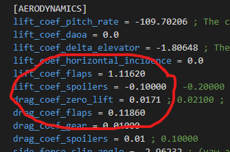
Here is the desired Cd0 of 0.0171 set in the flight_model.cfg file:
image


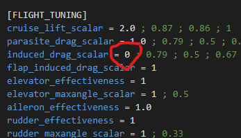
And here is the [FLIGHT_TUNING] section of the flight_model.cfg file:
image


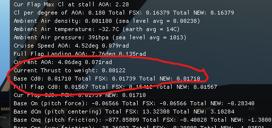
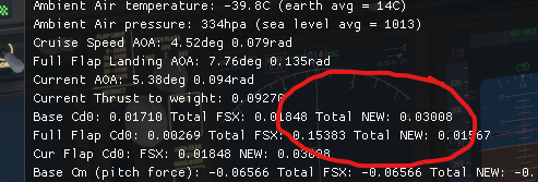
However, when looking at the numbers in the sim, here is what appears:
image

image


That Cd (Cx is the French notation for Cd) is way too high.
My manually calculated Cd for the conditions would be according to the SDK formula:
Cd = 0.0171 + k x 0.812² = 0,04796 (I voluntarily chose a Cl0 = 0), with k = 1/(PI x 8.46 x 0.804) = 0.04680
The difference between the sim and the manual calculation is huge: 0.07376 - 0.04796 = 0.0258.

After of lot of time, playing with the various parameters, I’ve come to realise that if the induced drag coefficient is set to 0 in the flight_model.cfg, then the correct Cd0 is calculated by the sim:
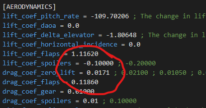
image

image

image


The induced drag shouldn’t have any influence over the Cd0 in the sim, but be added to it as the SDK says it does.
I hope this post was clear, and I hope this will get fixed at the next possible opportunity.

Thank you for reading me!
 

Lagaffe

Resource contributor
Messages
864
Country
france
Hi,
This flight model in spite of the 1000 points of calculation on which it is based is not finished: it drags a consequent batch of errors that of course editors can correct via VASM files but what will it be for the next versions if ASOBO decides to finally correct these numerous errors?
This could be the simulator that will have the most patches/corrections to be consistent on this aspect of physics.

As a proof for this assertion, an aircraft properly designed and parameterized to run perfectly on FSX (FDE), once the 3D model recompiled for MSFS still requires a considerable amount of work to "adapt" the flight model CQFD
 
Messages
15
Country
france
Yes, that's also what I've noticed.

I'm just sending the message out, on every platform, forum etc, so that Asobo takes notice and fix their bugs.

To be honest, I think that quite an accurate flight model could be achieved using the default one, that is once the bugs are corrected.
 
Messages
15
Country
france
Following up with the thread over at the MSFS forum :


I have found a temporary fix to this one, but it is really ugly and not really accurate.
The added value to what should be the Cd0 can be remove using the drag_coeff_zero_lift_tab by entering 0:X, with X being the correction value between the calculated Cd0 by the sim and your desired Cd0.
This allows to set the induced_drag_scalar to 1.0 and to have a decent amount of drag.
However, this cannot be considered the definitive solution. We need to have a clean Cd0 calculation by the sim, so that the drag can be fine tuned depending on its different components : parasitic drag, wave drag, induced drag, etc.
 
Messages
15
Country
france
So it turns out that this bug really isn’t one, but more a consequence of misleading labelling of the values in the debug windows. The value indicated as FSX and Total NEW are actually Cd(alpha = 0) and not Cd0, hence why they include the induced drag component of the Cl(alpha = 0).
However, there are still interesting things to be learnt from the experiment, for example how setting induced_drag_scalar = 0 influences how the drag_coef_gear is included or not in the Cd(alpha = 0) (cf results of the DA40NG).
I’m changing the title of this topic to reflect this.
 

Roy Holmes

Resource contributor
Messages
1,803
Country
us-virginia
I think you need to look at what the induced drag component of total drag includes. Specifically, it relates to CL, not Alpha where that is angle of attack.
If you consider an airplane flying level at 1 g, the value of CL naturally is positive. However the alpha to create that CL depends on the shape of the airfoil, in particular how much camber it has. My point is that alpha being zero needs some definition if comparing airfoils. In FSXA alpha is related to the fuselage axes whereas in earlier versions you had a value for the angle of the wing relative to the fuselage. What does MSFS use? Also values like wing aspect ratio mean something when the wing is a distinct structure and contributes almost all the lift. On many fighters the fuselage accounts for a lot of the lift especially when alpha is around 30 degrees. In these circumstances induced drag is pretty huge and most likely is incorrectly calculated by MSFS if the standard simplistic equations are used and are based on a distinct wing area value.
My point is that having the sim calculate its own flight dynamic values is OK for the simple types of airplanes favored by MSFS, but it should not automatically override the original values calculated or known by the designer.
An airplane with fixed gear obviously should include gear drag as part of the basic CD.
Roy
 
Messages
15
Country
france
Roy,

Thanks for contributing. My comment above is coming from the source: it is a reply from one of Asobo's developer to my question on their developer support website (link).

I understand the basics of lift and drag, however I can't have MSFS calculate the appropriate amount of drag for my project, and it seems that MSFS is underestimating the total drag of my plane.
 
Messages
244
Country
unitedkingdom
I can't have MSFS calculate the appropriate amount of drag for my project,
In case it helps... For sim sailplane design we can use SimPolars to establish from first principles what the lift/drag ratio must be and generally you can adjust things until those values are quite accurate across the speed range and payload settings (we spend WEEKS on this). We would have zero chance getting a flight model with the accuracy we want by watching a few simvars.

<rant>The stock DG808S in FSX is wrong by about 40% & the power planes are certain to have similar drag errors but the engine dominates flight performance anyway. Sim planes are never, ever flown engine off so the underlying drag is pretty irrelevant (ok, disagree with me, but maybe measure the drag first by looking at the engine off, flaps up sink rate across the speed range). As a (real) power modeller friend genuinely told me years ago: "with the right engine you can fly a plank"</rant>
 
Messages
15
Country
france
Hey,

I'm tuning the default 747 and I don't have this chart available unfortunately. However, I made an Excel file to calculate what the drag should be and compare it to MSFS drag. Here is the link: https://1drv.ms/x/s!AohwTJSZ0H8DgcEdzeuwq9Zj5EraZQ?e=kZAY9E

And here is a screenshot of the same file, showing the clear difference between what there is in the sim, and what the theoretical value should be:

1625650622664.png
 

jx_

Messages
555
Country
unitedstates
from briefly reviewing the OP I see problems:

1) You have to null out all those scalars. Any aircraft using non 1.0 scalars is wrong and the debug output is after scalars are applied. CDi is based on lift and you have lift doubled there, this could be what's throwing off your CD value.
2) In your text post and your spread sheet you are using different e values.
3) What is your mach drag set to? What speed are you at? Why is the current AoA different in both shots? Why is your CL alpha inconsistent with your 0.812? You haven't provided nearly enough info to form any conclusion.
4) Why do the sim values in your spreadsheet 'look' more like a B747 drag polar? I have never seen one symmetric as your theoretical line. Drag increases more rapidly with lift than with speed. On your drag polar lift is right and speed is left.
5) It also appears you have minimum drag at CL 0.1 which would be a really fast airspeed.


tips:
- First, do all your testing at sea level ISA, equivalent, or a consistent offset such as 10,000MSL ISA, then always convert your results to ISA!
- Second, use the real numbers, and learn what they mean. Don't fake it.
- Third, turn off the variables that get in the way.
- Fourth, math don't lie. Aerodynamics is 100% mathematical. There is no guess work, just adding or substracting to the coefficients. For many many years I have watched FS designers blame the sim. Get your numbers right first...then blame the sim!
- Crosscheck the values you see against raw aerodynamic values. For example, fly with engines on and measure the drag through thrust, then cut the engines off and measure the drag through descent rate. If something is not adding up in the fundamentals? Get the inputs right!
- Don't make the classic mistake of faking one number then chasing the error. FS9 through P3D have only 3 flight dynamics bugs yet 99.9% of designs for those platforms were built on faked numbers. Don't fall for it. Get your basic numbers correct FIRST!

Here's what you need to do...

1) correct all airplane geometry to the fuselage especially wing incidence. Be thorough.
2) correct all aero tables/fields to align with INSTALLED fuselage geometry. A big problem I see a lot is CL0 set to wing instead of fuselage, or CL alpha table set to wing instead of adjusted for incidence.
3) collect the actual numbers through documentation or analysis
4) put them into the sim in the right coefficient.


Using your numbers I was not able to establish anything consistent between any of your examples. That screams input error to me.
 
Messages
15
Country
france
from briefly reviewing the OP I see problems:

1) You have to null out all those scalars. Any aircraft using non 1.0 scalars is wrong and the debug output is after scalars are applied. CDi is based on lift and you have lift doubled there, this could be what's throwing off your CD value.
2) In your text post and your spread sheet you are using different e values.
3) What is your mach drag set to? What speed are you at? Why is the current AoA different in both shots? Why is your CL alpha inconsistent with your 0.812? You haven't provided nearly enough info to form any conclusion.
4) Why do the sim values in your spreadsheet 'look' more like a B747 drag polar? I have never seen one symmetric as your theoretical line. Drag increases more rapidly with lift than with speed. On your drag polar lift is right and speed is left.
5) It also appears you have minimum drag at CL 0.1 which would be a really fast airspeed.


tips:
- First, do all your testing at sea level ISA, equivalent, or a consistent offset such as 10,000MSL ISA, then always convert your results to ISA!
- Second, use the real numbers, and learn what they mean. Don't fake it.
- Third, turn off the variables that get in the way.
- Fourth, math don't lie. Aerodynamics is 100% mathematical. There is no guess work, just adding or substracting to the coefficients. For many many years I have watched FS designers blame the sim. Get your numbers right first...then blame the sim!
- Crosscheck the values you see against raw aerodynamic values. For example, fly with engines on and measure the drag through thrust, then cut the engines off and measure the drag through descent rate. If something is not adding up in the fundamentals? Get the inputs right!
- Don't make the classic mistake of faking one number then chasing the error. FS9 through P3D have only 3 flight dynamics bugs yet 99.9% of designs for those platforms were built on faked numbers. Don't fall for it. Get your basic numbers correct FIRST!

Here's what you need to do...

1) correct all airplane geometry to the fuselage especially wing incidence. Be thorough.
2) correct all aero tables/fields to align with INSTALLED fuselage geometry. A big problem I see a lot is CL0 set to wing instead of fuselage, or CL alpha table set to wing instead of adjusted for incidence.
3) collect the actual numbers through documentation or analysis
4) put them into the sim in the right coefficient.


Using your numbers I was not able to establish anything consistent between any of your examples. That screams input error to me.
Hi jx_,

Thank you for your contribution.

First, I want to clarify the conditions of testing. As you can see, this topic spreads over a few weeks and it started with me trying to modify the MSFS default 747 flight model. All testing was done in ISA conditions although at different altitudes.

To answer your points:

1) The lift scalar is set to 2, however, the lift vs mach table is set to the following: lift_coef_mach_table = 0:0.50, 0.43:0.64, 0.48:0.595, 0.60:0.75, 0.66:0.68, 0.8:0.92, and this was done as a remedial to allow me to increase lift with Mach number. Weirdly, only scalars lesser than 1 have an effect in this table.

2) The e value was changed many times, as I could not quite understand what MSFS what doing with the drag. But comparisons were made with the same e value. Actually, here is an updated Excel file that uses the default file values. The only modification that was done to the default file was changing the wing sweep, as it has a drastic effect on the drag calculation, and you can check it for yourself in this updated file: https://1drv.ms/x/s!AohwTJSZ0H8DgcE0rJVqZ-Fvre7j1A?e=w1pdlD

3) The Mach drag value is set to zero, and in the Excel file, I have M=Mcrit to zero it out. In the config files, it is zeroed as well.

4) My theoretical line is based on the SDK given quadratic formula: Cd = Cd0 + k(Cl-Cl0)², and that is my main point. Using this formula actually gives different results than the what simulator gives.

5) This is the default value, not mine.

I welcome your advice, and I have to say that this is all a learning experience for me. All of this is just me experimenting, making discoveries, getting right sometimes, wrong much more often, and sharing my results.

I would be happy to share my modified flight_model.cfg with you, if you fancy having a look at what I did, and why I did that way.

I invite you to play with the Excel file and the flight_model.cfg to see if you can get the simulator to agree with the Excel. I, so far, have been unsuccessful.
 
Last edited:
Top