• Which the release of FS2020 we see an explosition of activity on the forun and of course we are very happy to see this. But having all questions about FS2020 in one forum becomes a bit messy. So therefore we would like to ask you all to use the following guidelines when posting your questions:

    • Tag FS2020 specific questions with the MSFS2020 tag.
    • Questions about making 3D assets can be posted in the 3D asset design forum. Either post them in the subforum of the modelling tool you use or in the general forum if they are general.
    • Questions about aircraft design can be posted in the Aircraft design forum
    • Questions about airport design can be posted in the FS2020 airport design forum. Once airport development tools have been updated for FS2020 you can post tool speciifc questions in the subforums of those tools as well of course.
    • Questions about terrain design can be posted in the FS2020 terrain design forum.
    • Questions about SimConnect can be posted in the SimConnect forum.

    Any other question that is not specific to an aspect of development or tool can be posted in the General chat forum.

    By following these guidelines we make sure that the forums remain easy to read for everybody and also that the right people can find your post to answer it.

Import DXF (FSDS) to Blender...

Messages
13
Country
france
Hi all,

After a couple of years without any design I am coming back, not under FSDS but under Blender.
I am a real beginner with Blender and I would like to use the hard work already done under FSDS.
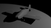
Therefore I have exported my FSDS Model under DXF format and imported it under Blender (see attachment).

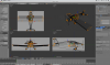
As you can see on the tailwheel screenshot there are only few visible points (orange), even if wireframe and model look fine.
I do not know how to get all the points visible?
Or may be the export under DXF format failed?

I am quite lost because under FSDS all the parts (i.e. fuse, gear, wing, tail, wheel, etc...) were distinctly named. Here under Blender I have only one part, which is the entire aircraft.
How do you proceed with parts? There is not enough layers (20) to manage parts. Where to go for part naming and family attachment (i.e. tyre attached to wheel attached to gear attached to fuse, etc...)?

Sorry to bother you with all my basic queries!

Sincerely.
 

Attachments

  • Capture d’écran 2014-02-25 à 16.37.13.png
    Capture d’écran 2014-02-25 à 16.37.13.png
    397.3 KB · Views: 918
  • Capture d’écran 2014-02-25 à 19.08.49.png
    Capture d’écran 2014-02-25 à 19.08.49.png
    27 KB · Views: 759

Dutcheeseblend

Resource contributor
Messages
1,541
Country
netherlands
Right, there we go! By the way, are you aware you're in Edit mode (Tab)?
Parts can be managed in the top-right window, which is a hierarchy viewer. There you can change names and so on.


Families are done as follows:
Select the tyre
Shift+select the wheel
press Ctrl+P and click 'Object'


Now, the tyre is placed in the tree, 'inside' the wheel.


Please, the problem of the imported object, try to replicate it with a easier object and put it here. Then we can have a look at it;)

If you have any questions, feel free to ask!

We'll be hearing of you!
 

arno

Administrator
Staff member
FSDevConf team
Resource contributor
Messages
32,883
Country
netherlands
Hi,

You could also try if importing goes better if you use ModelConverterX to turn your fsc file into 3ds. The dxf format is a bit limited.
 
Messages
13
Country
france
Dutcheeseblend,

Thanks a lot!
Because you spoke about part hierarchy, I went to the top right corner and found that there were two different parts.
One with few vertices only (the one I show you yesterday) and one with all vertices, edges and faces.
I have deleted the first one and now I have a complete part (see first attachement).
I have also renamed it as "SONEX" with one part only named "SONEX_Complete".
I can select the vertices I want.
Now I need time because I have to work as a Swiss clock maker by separating all parts...
Anyway, thanks Arno, but now it works!

I understood your explanation about family management, but I have tried to add a cube in the scene but it does not appear in the top right corner (see second attachment).
I thought it went automatically below the line Sonex.
How to see all parts like in your first screenshot where I can see Lamp, Camera, Tyre and Wheel?

Sincerely.
 

Attachments

  • Capture d’écran 2014-02-26 à 09.44.26.png
    Capture d’écran 2014-02-26 à 09.44.26.png
    528.7 KB · Views: 558
  • Capture d’écran 2014-02-26 à 09.44.52.png
    Capture d’écran 2014-02-26 à 09.44.52.png
    19.4 KB · Views: 600
Messages
13
Country
france
Dutcheeseblend,

Is there any way to hide vertices or edges or faces?
It is very difficult and long to separate all parts from the main one, pieces by pieces, therefore it will be helpful to have the possibility to hide vertices or edges or faces, in order to select the right vertices to declare a single part.

Sincerely.
 

Dutcheeseblend

Resource contributor
Messages
1,541
Country
netherlands
Simply via H, and unhide with Alt-H. I'll try looking at the other problem tonight.

Seperating for example a wing, is done by selecting all the vertices that are a wing, press P. Now the vertices form a seperate object.
 
Messages
13
Country
france
Dutcheeseblend,

I have tried H and P commands, both work like a charm!
Many thanks fo your very prompt support.

Sincerely.
 

Dutcheeseblend

Resource contributor
Messages
1,541
Country
netherlands
I understood your explanation about family management, but I have tried to add a cube in the scene but it does not appear in the top right corner (see second attachment).
I thought it went automatically below the line Sonex.
How to see all parts like in your first screenshot where I can see Lamp, Camera, Tyre and Wheel?

Designair,

Glad things work now!

Adding another object in Edit mode (menu highlighted in red below) will add the object IN the active object which you're editing. As you can see, I added a sphere to a cube, which is circled with green and marked so in the hierarchy viewer. Obviously it is now one object.
Adding the sphere in Object mode (from the red highlighted menu), means you'll be adding an NEW object. This is now proper visible in the hierarchy viewer as a seperate object. Both the object and it's place in the hierarchy are marked purple.


I hope this was helpful to you! And keep going with this nice little plane! Blender offers a lot of possibilities, IMHO, and modelling is quite easy.

Small note: basically, Object mode is used for animating, moving so in short manipulating the object. Edit mode is used for modelling, and in fact for vertex/edge/face manipulation.
 
Messages
13
Country
france
Dutcheeseblend,

Many thanks for your very clear support. I have understood 100% ;o)
I am working on part separation, which should take some hours...
Then I will start to try some animation (i.e elevator, aileron and rudder).
Probably I will come back to you for animation, especially for tail gear with a lot of small parts.

Later on, I will need also some help about rendering, because I have tried to get a nice screenshot like yours with light grey shinny aircraft and dark grey backdrop with shadow, using lamp and camera, but it was a mess...

Sincerely.
 

Dutcheeseblend

Resource contributor
Messages
1,541
Country
netherlands
Hi,

Great! Take care with animations, they should be with linear interpolation!

Anyway, start feeling comfortable with Blender now. I'd advice you not to put your main focus on rendering, since this is of very little interest for Flight Simulation. Though rendering is fun, I admit:D
 
Messages
13
Country
france
Dutcheeseblend,

I am separating all parts from my single main part... boring!
Anyway, I found some tricky things (see attachment).
In fact where I have a simple rectangle in Model Mode, I have a lot of faces coming from nowhere in the Edit Mode, which crete a lot of triangles.
My fear is about texture. What's happen with such overlapped faces?
Probably you do not you "Smooth" option for wings and tail.
Today my question is "shall I go ahead with my DXF import" or "do I have to start my project from scratch"?

Another question, about the VC.
Do you build your VC in the same Layer than the outside view parts, or do you create a new Layer for VC only?

Finally, is it possible to import a single part into the opened project?

Have a nice week-end.
 

Attachments

  • Capture d’écran 2014-03-01 à 12.45.18.png
    Capture d’écran 2014-03-01 à 12.45.18.png
    54.7 KB · Views: 680
  • Capture d’écran 2014-03-01 à 12.45.50.png
    Capture d’écran 2014-03-01 à 12.45.50.png
    71.1 KB · Views: 628
  • Capture d’écran 2014-03-01 à 12.57.50.png
    Capture d’écran 2014-03-01 à 12.57.50.png
    184.6 KB · Views: 691

Dutcheeseblend

Resource contributor
Messages
1,541
Country
netherlands
Right!
First, as in the second screenshot, you could delete those edges and create faces following the orange lines you were drawing. That's done by selecting 4 vertices, push F and there it is! Obviously, the triangles create a bad looking flaw at that location, as can be seen in the third screenshot.

Object mode doesn't always show all faces, that's why you don't see them there until in Edit mode. So the big face could be all those triangles, if you understand.

The VC is made in a seperate model, not a seperate layer, because it has a different GUID.

Importing parts from another Blender file is done via File, Append. Then you can browse until you find the file, hit it, and after that you can find in the folder 'Objects' anything you're looking for. Importing is done via the File, Import function. This brings no harm to your file you're working in!

Finally, I don't fully understand what you mean with Smooth. Please explain. Normally, Modifiers are not shown in Edit mode (not as editable anyway) though they do appear in Object mode. Quite logically of course! So it can happen that in Object mode you see a sphere, but editing you'll find a cube. Just the matter of Modifiers;)

Hope this helps out! Hint: there are a lot of Blender tutorials, you might try out a few of them to get used to all things. One (moving) picture tells more than a thousand of words, we'd say in Dutch;)

Wish you luck! And feel free to ask!
 
Messages
13
Country
france
Dutcheeseblend,

First I would like to thank you for your very kind, strong and prompt support!

I understood all of your comments and I can go ahead accordingly.
Except, what is the GUID for external model and the GUID for VC?
About "Smooth", in FSDS it was nice to smooth round parts (i.e. fuselage) but not flat parts (i.e. wings), therefore I though it was identical under BLENDER. As you said "Smooth" is available for Object Mode only, so no way. It means that you use "Smooth" when your model is complete and you apply it to the whole model, isn't it?
Of course I am watching a lot of video tutorials, but sometime I have some particular question for you ;)

One question about Scale: all the parts must have logically the same value for X, Y and Z in Scale?
Otherwise there is a distortion, isn't it?

Sincerely.
 

Dutcheeseblend

Resource contributor
Messages
1,541
Country
netherlands
No problem;)

The GUID is a ..err.. a GUID for FSX, which needs to be generated using the Blender2FSX toolset. FSX loves using GUIDs, and since both the internal and external model are different models, they will need a different GUID.

Well, smoothing (we BlenderBoys would say: SubSurfing) is OK, but use it wisely. Never apply before you're sure it's OK! You need to set the Crease (N, section Transform, in Edit) of certain edges to 1 sometimes when using a Subsurf modifier. Try experimenting with it, seeing what you're doing works best! Ah, and the Mirror modifier is wonderful! You need to do only the half of the work:p

Scaling can cause 'serious' problems, so keep the scale to 1,1,1! Always! If one part is not, press Ctrl A and hit Scale. This will reset the scale of an object. Also after merging (Ctrl J) of two objects, do this.

Bonne chance!
 
Top