• Which the release of FS2020 we see an explosition of activity on the forun and of course we are very happy to see this. But having all questions about FS2020 in one forum becomes a bit messy. So therefore we would like to ask you all to use the following guidelines when posting your questions:

    • Tag FS2020 specific questions with the MSFS2020 tag.
    • Questions about making 3D assets can be posted in the 3D asset design forum. Either post them in the subforum of the modelling tool you use or in the general forum if they are general.
    • Questions about aircraft design can be posted in the Aircraft design forum
    • Questions about airport design can be posted in the FS2020 airport design forum. Once airport development tools have been updated for FS2020 you can post tool speciifc questions in the subforums of those tools as well of course.
    • Questions about terrain design can be posted in the FS2020 terrain design forum.
    • Questions about SimConnect can be posted in the SimConnect forum.

    Any other question that is not specific to an aspect of development or tool can be posted in the General chat forum.

    By following these guidelines we make sure that the forums remain easy to read for everybody and also that the right people can find your post to answer it.

Magnetic Compass Gauge

Messages
184
Country
germany
Hi folks!

I tried to create a magnetic compass.

The problem is the positioning of the the scale map. I did a Nonlinearity

check with the two North positions, but it never functions correct.

Also, the compass stripe moves through other gauges, sure, its a long thing.

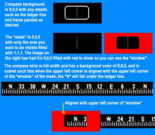
I rode something about mask images, but when I use it, the compass freezes.

Man Man, why can those ace folks it not do easier?!
 

n4gix

Resource contributor
Messages
11,674
Country
unitedstates
Maybe this will help:

compassgaugepartsrn5.jpg
 
Messages
184
Country
germany
Hi!

I got a basic version running now.

My biggest problem is the alignment. The compass never does what I want.

Somehow I have the feeling the trouble can be solved with these lines:

<Scale>1.000,0.000</Scale>
<Expression id="Expression">
<Script>(A:Wiskey compass indication degrees,degrees) dnor 593 * 360 / 593 -</Script>

What is this dnor 593*350 / 593 Relationship?
Can I move the upper left corner of the strip with that Scale Coordinates?


Greetings
 

n4gix

Resource contributor
Messages
11,674
Country
unitedstates
I got a basic version running now.

My biggest problem is the alignment. The compass never does what I want.

Somehow I have the feeling the trouble can be solved with these lines:

<Scale>1.000,0.000</Scale>
<Expression id="Expression">
<Script>(A:Wiskey compass indication degrees,degrees) dnor 593 * 360 / 593 -</Script>

What is this dnor 593*350 / 593 Relationship?
Can I move the upper left corner of the strip with that Scale Coordinates?


Greetings

That is "normalizing" 360º across a 593 pixel width. Replace 593 with whatever width your slider bitmap uses.

No, the <Scale> is simply what it is: it means "use the full width" when computing the scale.
 
Messages
184
Country
germany
Aaah!

I really think we get closer to the end of the tunnel.

Normally this formula is NDOR A * 360 / B.

So what is A and what is B. I saw this two variables differ from another

in other gauges.

So A is the STRIP LENGTH and B is the GAUGE PIXEL WIDTH (Geometry)?

Greetings
 

n4gix

Resource contributor
Messages
11,674
Country
unitedstates
Unless something is "weird" with those "other gauges," both A and B should be identical.

After all, what we are effectively calculating is the amount of movement in pixels for 1 degree, on the slider element, then multiplying the result by the pixel width, then normalizing the final result.

For example, if the strip width is 360 pixels, then the formula will of course calculate that for each degree of change, the stip should "slide" one pixel...

In the example you cited, the calculations would yield:

360/593 = 0.6070826

593 * 0.6070826 = 359.999998

dnor (359.999998) = 360

Unless "A" and "B" are equal, the final result would never be 360º... :eek:
 
Messages
184
Country
germany
Yes...

..I was testing what the variables mean. Dont mention it.

So my Scale Strip is 593 pixels in width.

The texture background of the gauge is 160 pixels in width.

Is the texture background also important?

(I didnt understand all of the calculating again!!!)

Greetings
 
Messages
184
Country
germany
I found out...

...the DNOR A*360/B

the variable A is the pixel distance between the two norths.

But what is B, that is always differing, but not much?!

Greetings
 
Messages
184
Country
germany
This is a default gauge of FSX

<?xml version="1.0" encoding="utf-8" ?>
- <Gauge Name="Compass" Version="1.0">
<Image Name="Compass_Background.bmp" ImageSizes="65,55,104,88" />
- <Element>
- <MaskImage Name="Compass_Background.bmp" ImageSizes="65,55,104,88">
<Axis X="34" Y="38" />
</MaskImage>
- <Image Name="Compass_Linear_Card.bmp" ImageSizes="260,15,416,24">
- <Nonlinearity>
<Item Value="0" X="233" Y="14" />
<Item Value="180" X="127" Y="14" />
<Item Value="360" X="24" Y="14" />
</Nonlinearity>
</Image>
- <Shift>
<Value>(A:Wiskey compass indication degrees,degrees) dnor</Value>
</Shift>
</Element>
- <Mouse>
<Tooltip ID="TOOLTIPTEXT_WHISKEY_COMPASS" />
</Mouse>
</Gauge>

The dont even use numbers behind DNOR

and what are these strange ImageSizes="65,55,104,88 ???

Im confused!

Greetings
 

n4gix

Resource contributor
Messages
11,674
Country
unitedstates
...the DNOR A*360/B

the variable A is the pixel distance between the two norths.

But what is B, that is always differing, but not much?!

Greetings

As I said, "...unless there's something wierd..."

IF the strip is properly constructed, then A and B should always be equal.

By "properly constructed" I simply mean that the distance in pixels from the left edge to the left "North" and the distance in pixels from the right edge to the right "North" is exactally the same.
 

n4gix

Resource contributor
Messages
11,674
Country
unitedstates
<?xml version="1.0" encoding="utf-8" ?>
- <Gauge Name="Compass" Version="1.0">
<Image Name="Compass_Background.bmp" ImageSizes="65,55,104,88" />
- <Element>
- <MaskImage Name="Compass_Background.bmp" ImageSizes="65,55,104,88">
<Axis X="34" Y="38" />
</MaskImage>
- <Image Name="Compass_Linear_Card.bmp" ImageSizes="260,15,416,24">
- <Nonlinearity>
<Item Value="0" X="233" Y="14" />
<Item Value="180" X="127" Y="14" />
<Item Value="360" X="24" Y="14" />
</Nonlinearity>
</Image>
- <Shift>
<Value>(A:Wiskey compass indication degrees,degrees) dnor</Value>
</Shift>
</Element>
- <Mouse>
<Tooltip ID="TOOLTIPTEXT_WHISKEY_COMPASS" />
</Mouse>
</Gauge>

The dont even use numbers behind DNOR

and what are these strange ImageSizes="65,55,104,88 ???

Im confused!

Greetings

This is a form of gauge for FS2004. In that version, 640X480 resolution was still supported, so you were allowed to have TWO sets of textures for each gauge: one low-res set (the smaller number pair) and one hi-res set.

In fact, we no longer even need to specify any "ImageSizes" entries...

However, since this method still works in FS9 and FSX, you can use this same format if you find it easier to understand.

Simply omit the lo-res numbers from the declarations:

<Image Name="Compass_Background.bmp" ImageSizes="104,88" />

The reason why only "dnor" is needed is because the ImageSizes were specified up at the top... :)

The "formula" we've been discussing is only needed with the "new" XML schema, since "ImageSizes" is no longer used...

Is this more clear?
 
Messages
184
Country
germany
Yes, you are my hero.

I will try I the old style first do understand it completely.

When I see how it works, I will inspect the new version.

Or could it be, LOL, that I make things to complicated?

We will see. I will come back tomorrow and tell you if it worked.

Thank you!

(Its getting night in europe)
 
Messages
184
Country
germany
Good Morning!

In this morning I tried the new code:

<?xml version="1.0" encoding="utf-8"?>
<Gauge Name="Compass" Version="1.0">
<Image Name="magnetic_compass_bg.bmp" ImageSizes="160,35"/>
<Element>
<MaskImage Name="magnetic_compass_window.bmp" ImageSizes="160,35">
<Axis X="87" Y="14"/>
</MaskImage>
<Image Name="magnetic_compass_strip2" ImageSizes="593,35">
<Nonlinearity>
<Item Value="0" X="87" Y="14"/>
<Item Value="180" X="296" Y="14"/>
<Item Value="360" X="505" Y="14"/>
</Nonlinearity>
</Image>
<Shift>
<Value>(A:Wiskey compass indication degrees,degrees) dnor</Value>
</Shift>
</Element>
<Mouse>
<Tooltip ID="TOOLTIPTEXT_WHISKEY_COMPASS"/>
</Mouse>
</Gauge>


Now the compass turns perfectly, with out becoming black and so on...

...but it still shows not the correct direction!

Can it be that Mask Image Axis, that makes the difference?

Or do I need to manipulate the dnor variable?

Greetings
 
Messages
184
Country
germany
Got the compass now running correctly...

...so after a full 360 turn north comes again up, but the scale rotates in
the wrong direction, so when there is real 30 in the sim, the compass is
at 330. Is there a special command to change the rotation direction?

Greetings
 

n4gix

Resource contributor
Messages
11,674
Country
unitedstates
...so after a full 360 turn north comes again up, but the scale rotates in
the wrong direction, so when there is real 30 in the sim, the compass is
at 330. Is there a special command to change the rotation direction?

Greetings

Oddly enough, I ran across this same problem (again) yesterday in a C version of a compass...

The solution is quite simple, actually. You simply need to multiply the variable used by -1 to reverse the rotation:

<Value>(A:Wiskey compass indication degrees,degrees) -1 * dnor</Value>
 
Messages
184
Country
germany
Sorry LOL...

...but I was not as clever!

I took the artist approach and repainted the texture in reverse.

But it also works the same way LOL.

So much trouble for a such small gauge, crazy or?

But now there is more experience and the next challenges are waiting!

THANK YOU

VERY VERY VERY MUCH!!!!

I hope I can help you some day too!

Greetings
 
Top