-
Which the release of FS2020 we see an explosition of activity on the forun and of course we are very happy to see this. But having all questions about FS2020 in one forum becomes a bit messy. So therefore we would like to ask you all to use the following guidelines when posting your questions:
- Tag FS2020 specific questions with the MSFS2020 tag.
- Questions about making 3D assets can be posted in the 3D asset design forum. Either post them in the subforum of the modelling tool you use or in the general forum if they are general.
- Questions about aircraft design can be posted in the Aircraft design forum
- Questions about airport design can be posted in the FS2020 airport design forum. Once airport development tools have been updated for FS2020 you can post tool speciifc questions in the subforums of those tools as well of course.
- Questions about terrain design can be posted in the FS2020 terrain design forum.
- Questions about SimConnect can be posted in the SimConnect forum.
Any other question that is not specific to an aspect of development or tool can be posted in the General chat forum.
By following these guidelines we make sure that the forums remain easy to read for everybody and also that the right people can find your post to answer it.
You are using an out of date browser. It may not display this or other websites correctly.
You should upgrade or use an alternative browser.
You should upgrade or use an alternative browser.
Tips and tricks from an idiot savant
- Thread starter ErickC
- Start date
- Messages
- 212
- Country
-

They're already starting to come standard with some payware releases (namely 3DTrains and Dekosoft) and there are some Soviet locomotives that have them as well. I've been using a chopped-down version of my GP10 external model to test all the new cab features and figure out the processes. As-is, I have all controls, engine gauges, and the speedometer functioning. I am reading through the manual and there's a whole load of information to absorb. It's overwhelming, but has the benefit of transparency: they explain each parameter as well as the theory and calculations used. Imagine if we had documentation that thorough for ESP!
The new features are insane. You can add a freight animation as before, but you can also tell the sim how much the freight weighs, you can have it be static (always there) or continuous (loadable and unloadable with a setting for what is default in each car), you can use more than one (for, say, a double-stack car), and you can even unload coal porters in rotary dumpers!
The new features are insane. You can add a freight animation as before, but you can also tell the sim how much the freight weighs, you can have it be static (always there) or continuous (loadable and unloadable with a setting for what is default in each car), you can use more than one (for, say, a double-stack car), and you can even unload coal porters in rotary dumpers!
Heretic
Resource contributor
- Messages
- 6,830
- Country
-

Motivation permitting, I might check out what Open Rails has to offer for the local market. MSTS did have some cool (sadly payware) retro lines from the other (i.e. my) side of the wall.
Still dreaming of a rendition of pre-war Berlin with all of its S-Bahn, U-Bahn, tram and bus lines to be ridden in first person. But there's no way in hell I can pull this off until I'm fish fodder.
Still dreaming of a rendition of pre-war Berlin with all of its S-Bahn, U-Bahn, tram and bus lines to be ridden in first person. But there's no way in hell I can pull this off until I'm fish fodder.
- Messages
- 502
- Country
-
Hi Folks,
Personally - some my favorite features ORTS brings to the table are the AI improvements - you can have AI switchers making and breaking trains - have the road locomotive link up and take the train to its destination and reverse the process - AI helpers coming and going on hills without user intervention - some real improvements over MSTS... It's pretty amazing what can be accomplished when a sim is developed as a community labor of love without corporate budget constraints to consider...
Been meaning to try Blender myself... My modeling efforts are very crude compared to Erick's and a tad older... Largest US Consolidation ever made...

Regards,
Scott
Sent from my iPad using Tapatalk
Last edited:

- Messages
- 212
- Country
-
Small post, relatively new technique for me:

It's a lot easier than doing it in an image editor. Faster, too, even though I'll have to take large screen caps and reduce the image size to maintain most of the original image's clarity...
Long way to go on this cab, though:

For this big old chunk of metal:

With any luck, it might pay for some books? College ain't cheap.
It's a lot easier than doing it in an image editor. Faster, too, even though I'll have to take large screen caps and reduce the image size to maintain most of the original image's clarity...
Long way to go on this cab, though:
For this big old chunk of metal:
With any luck, it might pay for some books? College ain't cheap.

- Messages
- 15
- Country
-
REFERENCES
Ebay. 20 bucks. It sits in my nightstand.
re: Your DC-9 Maintenance Manual
Wish I had one of these - no luck so far with eBay except multi-volume sets for $1,000 [sigh]...
Question for you: According to textbooks the "Angle of Incidence" of a wing is designated as "i(sub)wing" and defines the "Wing Reference Plane" aka WRP. I have a DC-9 diagram (front view) that depicts a downward-angled dotted line beginning outboard of the wingtip and ending at the wingtip. It is labelled "Wing Reference Plane." This appears to indicate that the WRP is a plane through the wingtip chord and root chord.
However, a graph of the DC-9 wing depicts the wingtip Angle of Incidence as -1.0 degrees, rather than 0 degrees per the above paragraph.
Given the fact that the angle of incidence varies along the wing semispan, I can't find an accurate definition as to the location of the WRP. Using the XY-plane of the designated aircraft coordinate system would seem to be the simplest method, but who knows what "tradition" has chosen.
Any help in defining this term would be GREATLY appreciated!
Tom
- Messages
- 212
- Country
-
On station diagrams, the wing reference plane is completely arbitrary with respect to any aerodynamic terms. On the diagram, the wing is depicted as it would be if it were flat and laying horizontally on the ground, without respect to dihedral (which shortens the wing span in terms of the overall dimensions of the airplane). The wing reference plane, you will notice, matches the dihedral of the wing. This lets you know that the actual wing is angled a few degrees and that the station diagram ignores the wing's dihedral. Therefore, you should build the wing flat, according to the station diagram, and then tilt it to the proper angle (this includes incidence as well as dihedral), or you will have inaccurate results (with the discrepancy growing with greater dihedral angles - simple trigonometry).
The incidence of the DC-9s wing varies as a function of span percentage, as an earlier post showed. The thickness does as well (it's not a linear relationship; there is a kink at the vortilon). The wing reference plane doesn't matter here, outside of its angles defining the wing's dihedral and incidence, because it's just a reference for the station diagram. Bear in mind that the variation of incidence of the airfoil is a function of skin contour, not wing structure.
The incidence of the DC-9s wing varies as a function of span percentage, as an earlier post showed. The thickness does as well (it's not a linear relationship; there is a kink at the vortilon). The wing reference plane doesn't matter here, outside of its angles defining the wing's dihedral and incidence, because it's just a reference for the station diagram. Bear in mind that the variation of incidence of the airfoil is a function of skin contour, not wing structure.
- Messages
- 15
- Country
-
ErickC,
Thanks for your reply!
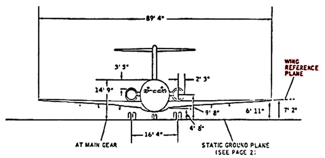
So the above diagram is correct, and the "Wing Reference Plane" is the plane from the Root Chord to the Wingtip Chord. The angle between the Wing Ref Plane and a horizontal plane is the wing Dihedral angle. One source I found states that the Dihedral for the "DC-9-50" is 1.5 degrees.
Tom
Thanks for your reply!
OK. The length of the wing on the STA diagram equals the length of the actual wing measured from fuselage to tip.On the [Station] diagram, the wing is depicted as it would be if it were flat and laying horizontally on the ground, without respect to dihedral (which shortens the wing span in terms of the overall dimensions of the airplane).
The wing reference plane, you will notice, matches the dihedral of the wing.
So the above diagram is correct, and the "Wing Reference Plane" is the plane from the Root Chord to the Wingtip Chord. The angle between the Wing Ref Plane and a horizontal plane is the wing Dihedral angle. One source I found states that the Dihedral for the "DC-9-50" is 1.5 degrees.
Tom
Attachments
- Messages
- 15
- Country
-
Building wings without guessing

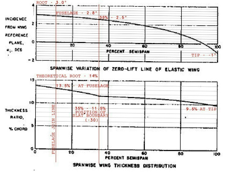
Questions on the above diagrams...
1. Is this the DC-9-10 series wing?
2. The top diagram depicts the Angle of Incidence of the Zero Lift Line, not the chord. I don't think so, but is there any way to determine the Geometric Angle of Incidence from this chart? That's what I'm looking for...is this info available anywhere?
Tom
- Messages
- 15
- Country
-
I think some of the diagrams posted in this thread are from this document: Does anyone have the entire "Aerodynamic Design of the DC-9 Wing and High-Lift System" by Roger D. Schaufele from 1967?
Heretic
Resource contributor
- Messages
- 6,830
- Country
-
1. Is this the DC-9-10 series wing?
https://en.wikipedia.org/wiki/McDonnell_Douglas_DC-9#Specifications
")
2. The top diagram depicts the Angle of Incidence of the Zero Lift Line, not the chord. I don't think so, but is there any way to determine the Geometric Angle of Incidence from this chart? That's what I'm looking for...is this info available anywhere?
Couldn't find any definite data. Roskam has "N/A" for the DC-9-50*, but lists 1.3° for the MD-80. Assuming that the MD-80's wing really just got an extension (see DC-9 family guide**) from the -41/50 and that the incidence change between the -41/33/34 and the older models was 1.25 degrees, one may assume that the original -10/30 did have hardly any incidence, if at all.
* https://books.google.de/books?id=bJlZ4mKf1EkC&pg=PA146&lpg=PA146&dq=jan+roskam+dc-9+incidence&source=bl&ots=AWknzyFNN1&sig=48N01Ktbu7TE74eooPKhPegCWw4&hl=de&sa=X&ved=0ahUKEwiksd3gyZTYAhWRIewKHY2VBpAQ6AEIMDAB#v=onepage&q=jan roskam dc-9 incidence&f=false
** http://airlinercafe.com/page.php?id=396
I think some of the diagrams posted in this thread are from this document: Does anyone have the entire "Aerodynamic Design of the DC-9 Wing and High-Lift System" by Roger D. Schaufele from 1967?
I only have Schaufele's other paper ("Aerodynamic Design Features of the DC-9") as a PDF.
You can buy the other here: http://papers.sae.org/670846/
What do you want to do with all that data anyway?
- Messages
- 15
- Country
-
1. There aren't any dimensions stated on the diagram. How can you tell if it's a -10 or not? I suspect it's the -10 because the diagram below it is designated -10, but the document also contains -30 diagrams.
Thanks. That's the same info that I have.Couldn't find any definite data. Roskam has "N/A" for the DC-9-50*, but lists 1.3° for the MD-80.
I purchased a copy from AIAA for $25, but my copy seems to be missing a number of diagrams that are referenced in "Aerodynamic Design of Transport Aircraft." I've notified AIAA, but they have not responded yet.I only have Schaufele's other paper ("Aerodynamic Design Features of the DC-9") as a PDF.
Thanks. That's where I found it for sale, but the price is $27. Having just spent $25 for nothing new, I was hoping that someone else had this one. Then I could find out if there was any data in addition to what was in "Aerodynamic Design Features of the DC-9."You can buy the other here: http://papers.sae.org/670846/
I have a 1/144th scale DC-9-30 kit that I'd like to improve. The wing shape is incorrect, so I'm compiling as much data as possible. If I can get enough information I'd like to scratchbuild a -30 in 1/72 or 1/48th scale.What do you want to do with all that data anyway?
Thanks for the info.
Tom
Heretic
Resource contributor
- Messages
- 6,830
- Country
-
1. There aren't any dimensions stated on the diagram. How can you tell if it's a -10 or not? I suspect it's the -10 because the diagram below it is designated -10, but the document also contains -30 diagrams.
Wingspan. The -30 and beyond all got wing extensions.
I have a 1/144th scale DC-9-30 kit that I'd like to improve. The wing shape is incorrect, so I'm compiling as much data as possible. If I can get enough information I'd like to scratchbuild a -30 in 1/72 or 1/48th scale.
Ah, nothing flight sim related then. I kind of hoped that you wanted to do something for one of the DC-9 renditions for flightsim use.
- Messages
- 15
- Country
-
The diagram I am referring to is in post 111. Span is only indicated as a percent value from 0 - 100%. The top chart is the zero lift line, and the bottom line is thickness distribution, both as a percentage of semi-span.Wingspan. The -30 and beyond all got wing extensions.
That's a possibility. IF I can get the data.Ah, nothing flight sim related then. I kind of hoped that you wanted to do something for one of the DC-9 renditions for flightsim use.
Are you looking for someone to improve the appearance of the DC-9 renditions, or the handling qualities?
Heretic
Resource contributor
- Messages
- 6,830
- Country
-
The diagram I am referring to is in post 111. Span is only indicated as a percent value from 0 - 100%. The top chart is the zero lift line, and the bottom line is thickness distribution, both as a percentage of semi-span.
Thought you were still discussing the wing reference plane.
Judging from the remark about the -30 in the lower diagram, I'd say that this is indeed intended for the -30.
Are you looking for someone to improve the appearance of the DC-9 renditions, or the handling qualities?
Flight dynamics, mostly. Do you have any development experience in FSX?
- Messages
- 15
- Country
-
The red text was added to the diagram by the poster. I believe that the "35%" comment refers only to the location of the vortilon on the DC-9-30. My experience is that unless the chart/diagram specifically states a different series, it refers to the -10. I *think* these charts are for the -10 because nothing is mentioned in the document regarding these two charts.Judging from the remark about the -30 in the lower diagram, I'd say that this is indeed intended for the -30.
IIRC, "Flight Dynamics" in this case refers to the aircraft not responding as intended. e.g. Flying through the ground rather than landing.Flight dynamics, mostly. Do you have any development experience in FSX?
FSX? No. Pre-FSX, yes; but it's been many years...
Heretic
Resource contributor
- Messages
- 6,830
- Country
-
The red text was added to the diagram by the poster. I believe that the "35%" comment refers only to the location of the vortilon on the DC-9-30. My experience is that unless the chart/diagram specifically states a different series, it refers to the -10. I *think* these charts are for the -10 because nothing is mentioned in the document regarding these two charts.
You can also clear this up by fetching good drawings of a -10 or -30 and measuring the wing thickness and chord and then comparing the T/C ratio with the above diagram. Since the -30's wing basically got a notable chord extension at the wing-fuselage-junction due to the slats (see Airliner Café's DC-9 guide), the resulting ratio should differ.
IIRC, "Flight Dynamics" in this case refers to the aircraft not responding as intended. e.g. Flying through the ground rather than landing.
No, not that. The rendition I'm using needs improvement in terms of aerodynamic. I doubt that a heavy DC-9-30 will still climb happily beyond FL350, if at all.
- Messages
- 15
- Country
-
Still looking for decent DC-9-30 drawings.You can also clear this up by fetching good drawings of a -10 or -30 and measuring the wing thickness and chord and then comparing the T/C ratio with the above diagram. Since the -30's wing basically got a notable chord extension at the wing-fuselage-junction due to the slats (see Airliner Café's DC-9 guide), the resulting ratio should differ.
The 6437 x 2638 version of this drawing will not download.
https://encrypted-tbn0.gstatic.com/...5JXN9ZxXOQ918GUKyiEbqtLKqflZV9rkyVtkrP0iSR3aA
Do you or anyone else have this drawing in its full size?
The "real thing" will DEFINITELY not reach 350 at a heavy weight. You have to "step climb." Does the climb rate 'fall off' at all as altitude increases after takeoff? If not, then generated lift is not decreasing as air pressure decreases with altitude.No, not that. The rendition I'm using needs improvement in terms of aerodynamic. I doubt that a heavy DC-9-30 will still climb happily beyond FL350, if at all.
What is atmospheric pressure and angle of attack at 350? AoA should be in the stall regime.