• Which the release of FS2020 we see an explosition of activity on the forun and of course we are very happy to see this. But having all questions about FS2020 in one forum becomes a bit messy. So therefore we would like to ask you all to use the following guidelines when posting your questions:

    • Tag FS2020 specific questions with the MSFS2020 tag.
    • Questions about making 3D assets can be posted in the 3D asset design forum. Either post them in the subforum of the modelling tool you use or in the general forum if they are general.
    • Questions about aircraft design can be posted in the Aircraft design forum
    • Questions about airport design can be posted in the FS2020 airport design forum. Once airport development tools have been updated for FS2020 you can post tool speciifc questions in the subforums of those tools as well of course.
    • Questions about terrain design can be posted in the FS2020 terrain design forum.
    • Questions about SimConnect can be posted in the SimConnect forum.

    Any other question that is not specific to an aspect of development or tool can be posted in the General chat forum.

    By following these guidelines we make sure that the forums remain easy to read for everybody and also that the right people can find your post to answer it.

mistake in shape file

Messages
170
Country
germany
Hi,

again I strugle with these new shape files:mad:
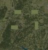
I generate atomaticly all grass strip in Baden-Württemberg. Most of them look perfekty, but I have some big mistakes in a few areas. Look at the picture.
I will get this mistake with FSXKML and with Mr. Orthmanns Exe.
Can soembody think what this mistake can be?

Thanks for help
Christoph
 

Attachments

  • BW_01.jpg
    BW_01.jpg
    89.9 KB · Views: 608
Hi Christoph,

I (and probably others too) are not able from the picture to guess what the mistakes are. What do you have at the outset, which data are you using, which procedures, and what do you want to accomplish?

Is it that you get the wrong size of the airstrips, or what?

Peter
 
Hi Christoph,

As Peter already indicates the question is not that clear indeed. I can see that the picture looks a little weird, but maybe you can tell a little more detailed what you want to accomplish?

You should see the shapefiles only as a dataformat. I use them a lot at work as well, but I think the problems you are seeing here have more to do with the compiler used to make the BGL and how it expects the data to the specified.
 
OK, I will, Sorry!

You can see a few sqares in the Picture with only one Landclass Texture.
Here is what I do:

I made one Airfields with two polies:
1. Runway (4 Points)
2. Airfields Underground (more than 4 Points)

I have a database with all glider airstrips and calculate all airstrips in a program an write all polies in XML file. I already did this into a KML file as well. In Google Earth everything looks fine. But after compilation I have these wrong polies in my bgl file.

Maybe there is a translation mistake by creating the shape files?

How should I draw my polies:

clockwise?

or opposite?

I hope this will help a bit more .
Thanks
Christoph
 
Hi Christoph,
How should I draw my polies: clockwise? or opposite?

Matters only when you draw polys with holes in them.

But I wonder why you are using shapes at all for the actual runways. I would suggest an xml/kml-file for the airport skirting, tagged appropriately (compiled with shp2vec) and then a normal APX-file for the runways. If you do not like the look of the available textures, you can simply make the width very small.

I have included a small example with the source files. This is a private airstrip on a small Danish island, existing in real, but not as a default in FSX. The APX was basically made with good old AFCAD and then manually adapted (not much adaption) and compiled with the new BGL Compiler. Even if you do not see the several parking spots, the AI aircraft do.

Peter
 

Attachments

Hi Peter,

the problem is, that we have several not flattened airstrips in GErman you can not realize withe the runway call. You also have to flatten the poly around the runway! But then the airfield looks not good any more. By using the two polies like this, I also have sloped runways:D

I think I solved the problem a bit. It works better by creating polies clockwise!
 
Hi Christoph,

The most important thing is that it works for you. (I still, however, do not not see why clockwise/anti-clockwise should matter in your case).

In the example I provided the main poly also flattens. If you want, you can make it at an angle (assign indiviual altitudes to the vertices). But the APX-system will still not let you make a sloped runway, I think. So if that is what you want, stick with what you have got.

Peter
 
The shapefile specification says:

"Vertices for a single, ringed polygon are, therefore, always in clockwise order."

so I would probably try to stay with that. In my little testing it seems shp2vec is kind of sensitive about that.

scott s.
.
 
The shapefile specification says:

"Vertices for a single, ringed polygon are, therefore, always in clockwise order."

so I would probably try to stay with that. In my little testing it seems shp2vec is kind of sensitive about that.

scott s.
.

Shp2Vec should accept either winding order. The winding of holes MUST, however, be opposite of the containing outer ring.

-Doug
 
Thanks for your comments. Sometime you only try by testing...
I hope I found now a way without producing other mistakes.
 
Back
Top