Hi Max:
IIUC, you have an 'acceptable' result that you are willing to work with.
")
Sorry I did not have more time available right now to prepare a more individualzed work-flow for you.

I did a fairly extensive search to see if there was any high resolution elevation data online for that area of Iceland, but found nothing acceptable; AFAIK, Iceland has thus far only generated a higher resolution GIS elevation data set for a few areas of the country, but not at that airport location.
So, IMHO, one would have to do a modified version of the approach your files (linked in a PM) showed you were starting to implement in SBuilderX.
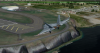
A modified version of the approach you had already begun to implement based on the visual demarcation of shoreline and terrain at the edge of the airfield seen in background imagery, would involve expanded extent- and/or increased numbers of- vector object TIN surfaces.
IIUC, you had planned to exclude and replace the FS default central airfield flatten in order to achieve a more
gradual slope for the terrain between the airfield and shoreline.
If you wanted a single slope that was less steep but with a
straight surface, you could use a
single row of triangles between the central airfield flatten and the shoreline.
Otherwise, if you wanted to have a
curved slope, you would likely need to use
2 or more rows of triangles between the central airfield flatten and the shoreline in oder to implement a desired ground surface 'shape'.
Doing these types of sloped flattens manually is labor-intensive, and there are other semi-automatic ways to do this with several FS utilities, and either a GIS or 3D modeling application.
Alternate options for further reducing workload may use a graphics application which can create and save discrete vector "Paths" generated from color-based selections of landmark areas in imagery by a "Magic Wand" feature.
Those "Path" vector objects may then be further processed via other software to make a more accurate interpretation of sloped terrain areas via processing of contour lines with assigned elevations into TIN 3D mesh surfaces, which can then be converted into a CVX vector sloped flatten BGL by Arno's MCX.
Hopefully I will find some time in the future to create a step-by-step guide to make such sloped flattens via
ex: SBuilderX, a color selection-to-vector Path output capable graphics application, and Sketchup.
")
As you may now be satisfied with having been '
pointed in the right direction, any step-by-step guide to make such sloped flattens I might eventually create will likely be posted elsewhere, but would likely be found via a Google Search of these forums such as I linked you to above, so if you are inclined to work with a "sloped flatten" in the future, perhaps even more helpful info may be available at that time.

GaryGB


 The topic is now closed