I guess I didn't really answer your question, did I?
Yes, it's possible to do this "by hand". Typically, I download high-resolution aerial imagery from the state's GIS website (most states in the US have one).
I then cut this imagery up into 1024x1024 squares, and apply them as textures to planes of appropriate size (1024ft by 1024ft, assuming 1ft source imagery). Don't forget to make sure that there are vertices every 1000ft or so (the 100 meter number often quoted is excessive and unnecessary).
From there, I start laying down splines - again, no gaps longer than 1000ft - using the background imagery as a template. This process is augmented by downloading the Airport Master Plan, which usually includes a very detailed Airport Layout Plan (ALP) drawing. This alsoc contains info on things like how wide taxiways are, and centerline-to-centerline distances between parallel taxiways and runways, etc.
For added realism, I also reference the FAA Advisory Circular Series 150 documents, that outline the standards for pavement design and marking. This will tell you what radius the pavement fillets should be, and the exact dimensions of every marking and feature you could ever want.
Using all of these sources, I recreate all of the pavement surfaces I wish to include, usually grouping the splines that represent a specific surface type together - i.e. I split up ramps and taxiways where they change from concrete to asphalt, or where there are noticeable changes in the pattern on the pavement. This makes texturing later much easier.
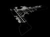
Finally, I apply an edit poly modifier to the stack, and that changes the splines into nifty poly's like you see in the screenshots above.
One other bit to point out: I see a lot of people using - or recommending the use of - bezier curves to recreate the taxiway/runway fillets. I think that manually manipulating the control points of spline to do this is the wrong way to go. It's almost impossible to get a constant radius curve using this method, and the result is usually a weird ellipse instead of a nice uniform curve.
Use the Arc tool instead, and use the Vertex and/or Perpendicular snaps to create a very realistic result. Simply "Add" the curve to the other spline sections, weld the verts, and there you go. Also, make sure to check "Optimize" and pump up the Iterations to "5" for normal curves and "7" or even "9" for very large radius curves. This will ensure that there are no ugly corners on what should be a very smooth curve.
Regards,
Nick


")