-
Which the release of FS2020 we see an explosition of activity on the forun and of course we are very happy to see this. But having all questions about FS2020 in one forum becomes a bit messy. So therefore we would like to ask you all to use the following guidelines when posting your questions:
- Tag FS2020 specific questions with the MSFS2020 tag.
- Questions about making 3D assets can be posted in the 3D asset design forum. Either post them in the subforum of the modelling tool you use or in the general forum if they are general.
- Questions about aircraft design can be posted in the Aircraft design forum
- Questions about airport design can be posted in the FS2020 airport design forum. Once airport development tools have been updated for FS2020 you can post tool speciifc questions in the subforums of those tools as well of course.
- Questions about terrain design can be posted in the FS2020 terrain design forum.
- Questions about SimConnect can be posted in the SimConnect forum.
Any other question that is not specific to an aspect of development or tool can be posted in the General chat forum.
By following these guidelines we make sure that the forums remain easy to read for everybody and also that the right people can find your post to answer it.
You are using an out of date browser. It may not display this or other websites correctly.
You should upgrade or use an alternative browser.
You should upgrade or use an alternative browser.
What is z-test and z-write?
- Thread starter MarkkuS
- Start date

 .
.- Messages
- 268
- Country

When a polygon is rendered to a pixel the distance from the polygon (at the specific pixel) to the "camera" is stored in something known as the z-buffer. When another rendered polygon covers the same pixel the distance from the new polygon to the camera is calculated and if it is futher away it's simply dropped - if it is close it is rendered to the pixel and the new distance to the camera is stored in the z-buffer.
The problem is that only one distance can be stored per pixel - so if you have for example a glass window with a wall behind the z-buffer can contain either the distance to the wall or the distance to the window. If it contains the distance to the wall and you render a polygon between the wall and the window the polygon will be closer than the distance stored in the zbuffer and the window will be overwritten (which makes it appear 100% transparent). If the z-buffer instead contains the distance to the window, the new polygon will be considered further away it will not be rendered at all.
ZTestAlpha, AlphaTestValue, and AlphaTestFunction can be used to control when a rendered polygon updates the distance stored in the z-buffer. As Arno mentions, read the SDK and ask if you have specific questions - no point in repeating the SDK here.
You can for example set it to write the value if the material is less than 10% transparent (no, I don't know the specific values needed).
Personally I have not had much luck messing with these values - the best result is if you can control the render order the objects are in (I do not know if GMax does this, I generate my own .X files). If objects are always rendered so polygons furthest away from the camera are rendered first, then the z-buffer will work as expected. Unfortunately you can't change the render order depending on the viewing angle in the FSX format, so if you have multiple levels of partial transparent polygons overlapping, you are unfortunately having a situation that the current generation of graphics cards simply can't deal with.
- Messages
- 34,316
- Country
To add what Lars said, I have had success with these settings in getting for example a fence to display with the correct drawing order (also with other objects behind it). It might take some tweaking, but you can solve the drawing order problems. And better than we could with the old FS2004 code.
- Messages
- 2,385
- Country

So far so good. Thanks anyway, because that was definitely more specific than the (otherwise very well done) SDK.
Question remaining is: what gives me more chances to see my transparent object in front of a semitransparent cloud: if I use a high z-buffer or a small? And which option (greater, less,...) do I have to choose? I cannot find that in the SDK.
EDIT: Wow, I just moved my mouse cursor across the image in the SDK for the first time - and guess what I found?
Last edited:
Hi,
I assume you already read the SDK on these options?
Yes, I have searched the FSX-SDK and found very little information on "z-write" and "z-test". On "z-write" I found something in "Modeling File Format" and on "z-test" one line in "New Aircraft Procedures. Nothing of this help me to understand the z-words.
Last edited:
- Messages
- 34,316
- Country
EDIT: Wow, I just moved my mouse cursor across the image in the SDK for the first time - and guess what I found?
Yes, those tooltips are the best part of the part about the material settings
") .
.
Thanks Arno!
I am working on moving all of our tool help to be more graphical like that. I expect the next SDK to be much, much better in terms of visual representations of what it is the tool or feature does.
Lars' description of Zwrite and Ztest is very good. I would add one thing, and that is that if you are trying to do soft 8-bit alpha, then ZTest will essentially force it to look like 1-bit alpha. This is because the Ztest is essentially binary. It will render the soft alpha, but it will also do the Ztest and write the pixels in front or back based on the Ztest. So a Ztest of GREATER and a value of 128 means it Zwrites when the alpha value is greater than 128. Which means it will write through all parts of the object that have that material applied when the alpha value is greater than 128.
If you want to do soft alpha that sorts correctly with everything in the scene, the only real way to do it is to create separate draw calls for those parts. An example is the windows on the heavies. We orginally tried to do those with 8-bit alpha in the texture. The problem is that if you ZWrite them, then they write through the interior of the plane and all you see is sky on the other side of the window. If you don't ZWrite them, then they are likely to sort incorrectly and some windows will look semi-transparent, while others won't draw at all. So you have to make separate geometry, apply a material to the windows and another material to the body and interior and then you'll get proper sorting. This is why the canopies, the bodies and the props are all different materials with different draw calls. They all need to be sorted independently of each other.
By the way, alpha sorting is still one of the most difficult problems to solve in 3d graphics. Especially if you have a completely open world like ours.
- Messages
- 2,385
- Country
Thanks for this clarification. Good to know that my workaround I used before (which was in fact creating different materials for some semitransparent objects) was not such a bad idea.
One thing I'd like to ask though: 128 - what does that mean? If I take a DXT3-image it gives me 8 steps of grey, erm, would that mean that 128+ is everything that's completely black in my alphamask?
One thing I'd like to ask though: 128 - what does that mean? If I take a DXT3-image it gives me 8 steps of grey, erm, would that mean that 128+ is everything that's completely black in my alphamask?
- Messages
- 268
- Country
I think the alpha channel is considered 8 bit, so 0-255. The encoding might not be able to represent all levels, but the stored value will be mapped to the 0-255 range. For example the DXT1 monocrome alpha channel will result in values of either 0 or 255.
On top of this anitializing (or something else the graphics card does, could be the filtering) can yield different values than 0 and 255 along the edge of the visible pixels in DXT1 texture. As a result if you use a really low value instead of 128 in your test, you can end up seeing a colored outline around your object.
On top of this anitializing (or something else the graphics card does, could be the filtering) can yield different values than 0 and 255 along the edge of the visible pixels in DXT1 texture. As a result if you use a really low value instead of 128 in your test, you can end up seeing a colored outline around your object.
- Messages
- 2,385
- Country
I am very, very sorry still not understanding this.
Does that now mean that the higher the value the less darker parts of my (DXT3) alpha mask will be displayed?
Does that now mean that the higher the value the less darker parts of my (DXT3) alpha mask will be displayed?
- Messages
- 34,316
- Country
Hi Thorsten,
If I read Adrian's answer correctly he is saying that the alpha channel of your DXT3 texture is rendered as normal, so no information is lost there. But for the testing what is shown through your transparent parts is done on a 1-bit way. So only behind the parts of your alpha channel that have an alpha value bigger than the testing value you enter they will display correctly. Behind parts with a lower value, you can still have the drawing order trouble as before.
So the display of the alpha channel is not 1-bit, but the testing for drawing order is.
I am very, very sorry still not understanding this.
Does that now mean that the higher the value the less darker parts of my (DXT3) alpha mask will be displayed?
If I read Adrian's answer correctly he is saying that the alpha channel of your DXT3 texture is rendered as normal, so no information is lost there. But for the testing what is shown through your transparent parts is done on a 1-bit way. So only behind the parts of your alpha channel that have an alpha value bigger than the testing value you enter they will display correctly. Behind parts with a lower value, you can still have the drawing order trouble as before.
So the display of the alpha channel is not 1-bit, but the testing for drawing order is.
- Messages
- 2,385
- Country
So if I want to ensure that my semitransparent object is drawn last I should give it a high z-test value? Gonna try this.
- Messages
- 2,385
- Country
I still don't understand that stuff. 
Now, I have one really crucial material in my scenes, that is the tower windows. They are of course 2-sided and there are always 2 behind each other if you look through the tower (as usual it's got glass all around). Then I have other parts of the tower and of course antennas behind the tower, that use alpha blend - and finally there are the semitransparent clouds in the sky.
Now, if I don't use any z-testing, it works reasonanbly well, but not perfect: the clouds still look a bit funny.
If I try to use z-testing, the windows do not show up at all.
Additional problem is that I cannot seem to get the environmental reflection going with the glass.
- Messages
- 34,316
- Country
Hi Thorsten,
Humm, I don't think it works like that. I am still a bit confused by it sometimes, but if I understand it well the level influences for which part or your texture (from which alpha value), the Z-testing is done differently. So then higher does not have to be better.
It is some time ago I played with this, I think there is a thread by Jon Patch with some good settings. If I remember correct it is a combination of the Z-testing, Z-write alpha and No Z write setting.
So if I want to ensure that my semitransparent object is drawn last I should give it a high z-test value? Gonna try this.
Humm, I don't think it works like that. I am still a bit confused by it sometimes, but if I understand it well the level influences for which part or your texture (from which alpha value), the Z-testing is done differently. So then higher does not have to be better.
Now, if I don't use any z-testing, it works reasonanbly well, but not perfect: the clouds still look a bit funny. If I try to use z-testing, the windows do not show up at all.
It is some time ago I played with this, I think there is a thread by Jon Patch with some good settings. If I remember correct it is a combination of the Z-testing, Z-write alpha and No Z write setting.
- Messages
- 2,385
- Country
Thanks Arno. Gonna look for that.
- Messages
- 2,385
- Country
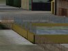
Maybe I can show some pictures to learn more about it.
See attached picture 1:
Transparent fences (DXT1) and glass windows (DXT3) work just perfect without any z-testing.
Now, picture 2: Fence and windows work well. Window also works quite nice with ground polygon (stones with DXT3 in order to blend the underlying photo texture), but the fence has not the correct layering. It's blended by the stones polygon.
(EDIT: Just recognized: the 2 fences on the left have also z-problems )
Now, how can I solve this by using the z-test?
See attached picture 1:
Transparent fences (DXT1) and glass windows (DXT3) work just perfect without any z-testing.
Now, picture 2: Fence and windows work well. Window also works quite nice with ground polygon (stones with DXT3 in order to blend the underlying photo texture), but the fence has not the correct layering. It's blended by the stones polygon.
(EDIT: Just recognized: the 2 fences on the left have also z-problems
)Now, how can I solve this by using the z-test?
Attachments

Last edited:
- Messages
- 34,316
- Country
Hi Thorsten,
Are this different MDL objects or is it all in one object? That might have some influence as well.
I would have to look at the settings again to see what works best. If you can't solve it, maybe we can take a look together? You know where to find me.
Are this different MDL objects or is it all in one object? That might have some influence as well.
I would have to look at the settings again to see what works best. If you can't solve it, maybe we can take a look together? You know where to find me
.- Messages
- 2,385
- Country
That's a good idea.
I'll be away for the weekend, but definitely will have to take another close look at it on monday.
Fence and windows are one MDL, ground polys (stones) another. I hoped that would help for the sorting order, but it seems that is not the case here.
I'll be away for the weekend, but definitely will have to take another close look at it on monday.
Fence and windows are one MDL, ground polys (stones) another. I hoped that would help for the sorting order, but it seems that is not the case here.