Follow along with the video below to see how to install our site as a web app on your home screen.
Note: This feature may not be available in some browsers.
Which the release of FS2020 we see an explosition of activity on the forun and of course we are very happy to see this. But having all questions about FS2020 in one forum becomes a bit messy. So therefore we would like to ask you all to use the following guidelines when posting your questions:
Tag FS2020 specific questions with the MSFS2020 tag.
Questions about making 3D assets can be posted in the 3D asset design forum. Either post them in the subforum of the modelling tool you use or in the general forum if they are general.
Questions about aircraft design can be posted in the Aircraft design forum
Questions about airport design can be posted in the FS2020 airport design forum. Once airport development tools have been updated for FS2020 you can post tool speciifc questions in the subforums of those tools as well of course.
Questions about SimConnect can be posted in the SimConnect forum.
Any other question that is not specific to an aspect of development or tool can be posted in the General chat forum.
By following these guidelines we make sure that the forums remain easy to read for everybody and also that the right people can find your post to answer it.
Hi everyone,
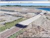
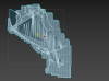
I've made the entire airport terrain mesh on 3DsMax to fix the orribile default mesh of my airport. I've exported this as custom flattern with Mcx the only problem see the aliasing of the terrain on long distance. Anyone knows a better way to do it?
My goals is to fix the coast mesh too and make some tunnels and terrain slopes. Thanks.
Can you show what you mean with the aliasing problem? Does that come from terrain textures that follow your new flatten or did you place a ground polygon on it as well?
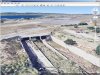
If you wish to add some more high detail terrain enhancement to the surrounding environment at LICR, you may need to use both custom local terrain mesh and a 3D model for this airports tunnels etc.
The 3D model of the navigable surfaces (ex: as a G-Poly) can be hardened with a attached "Platform" where they cross over a tunnel.
The CVX vector sloped flatten modifies display of elevation data points of any local terrain mesh.
The FS terrain grid 'quads' will always be subject to jagged edges and quad edge 'aliasing' as a function of aircraft camera distance associated with LOD switching.
So, in some areas, it is best to use a 3D model as a G-Poly that is placed on top of- and blended into- the sloped flatten terrain surface.
The 3D model G-Poly will allow greater control over LOD switching and display of straight edges etc., while allowing one to have tunnels that pass underneath the airport surface provided by the G-Poly,
The terrain surface under the 3D model G-Poly can be provided by the sloped flatten and/or a high-resolution custom terrain mesh BGL (made via SDK Resample from LiDAR elevation source data).
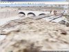
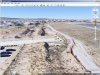
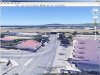
Some screenshots follow below, which are derived from examples seen in Google Earth Desktop Edition:
After installing Google Earth, and downloading the Reggio Calabria Airport.zip file linked immediately above, un-ZIP the archived *.KMZ file, then double-click it; allow it to load in Google Earth.
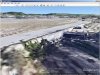
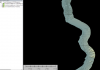
Here is how detailed such a LiDAR data set can be for your project location:
FYI: There is 1-Meter-between-elevation-data-points LiDAR source data available for this area.
AFAIK, both a DSM and DTM version of this data set is available.
"A high resolution LIDAR TOOLCARTOGRAPHY - Jul 31,2017 - 17 Comments
The Ministry of the Environment took over a slice of Italy and made the results available in high resolution. In this article I will explain the procedure for requesting and obtaining LIDAR data with 1 × 1 m mesh, a truly useful and powerful tool for geographical analysis, feasibility studies and preliminary projects of works in the area. Negligible expense, a few emails and a little waiting ..."
Geoportale Nazionale - Il Visualizzatore Cartografico consente la visualizzazione e l'utilizzo della cartografia di base nazionale. L'Italia a portata di click!
www.pcn.minambiente.it
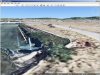
If processed via a GIS application and compiled via SDK Resample, you can make a high resolution custom local terrain mesh, and use a triangulated sub-set of the data for a 3D model and sloped flatten that fits seamlessly together with the custom terrain mesh.
PS: If you do create a version of this scenery using 1 Meter resolution elevation data, and you want to see how much the edges of CVX vector objects can be rendered in P3D without as much aliasing, you can enable a higher resolution terrain grid independently from that provided via the internal resolution of a terrain mesh BGL either by setting P3D GUI Terrain Mesh Resolution slider to 1 Meter, or by editing parameter values in the 'active' Prepar3D.Cfg file.
I recommend P3D GUI Tessellation slider be set to a max. Right position for max. terrain rendering precision:
* Tessellation Factor(aka "Terrain Mesh Complexity" in MSFS) at 100 %
If you wish, you can enable an even higher resolution terrain grid independently from that provided via the internal resolution of a terrain mesh BGL; this will create more closely-spaced grid vertices onto which vector objects and terrain mesh data can be displayed with less aliasing (...as a function of the FS rendering engine quad 'tile' infrastructure).
Assuming you have at least a DX-11 video card, in Prepar3D.Cfg, you may wish to test:
[TERRAIN]
LOD_RADIUS=3.500000 TESSELLATION_FACTOR=100 ; Tessellation Factor is aka "Terrain Mesh Complexity" in MSFS2Kx
MESH_RESOLUTION=25 ; 25 = 1.2 M, 26 = 60 cm, 27 = 30 cm, 28 = 15 cm, 29 = 7.5 cm, 30 = 3.75 cm
TEXTURE_RESOLUTION=30
If you wish to add some more high detail terrain enhancement to the surrounding environment at LICR, you may need to use both custom local terrain mesh and a 3D model for this airports tunnels etc.
The 3D model of the navigable surfaces (ex: as a G-Poly) can be hardened with a attached "Platform" where they cross over a tunnel.
The CVX vector sloped flatten modifies display of elevation data points of any local terrain mesh.
The FS terrain grid 'quads' will always be subject to jagged edges and quad edge 'aliasing' as a function of aircraft camera distance associated with LOD switching.
So, in some areas, it is best to use a 3D model as a G-Poly that is placed on top of- and blended into- the sloped flatten terrain surface.
The 3D model G-Poly will allow greater control over LOD switching and display of straight edges etc., while allowing one to have tunnels that pass underneath the airport surface provided by the G-Poly,
The terrain surface under the 3D model G-Poly can be provided by the sloped flatten and/or a high-resolution custom terrain mesh BGL (made via SDK Resample from LiDAR elevation source data).
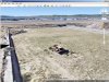
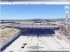
Some screenshots follow below, which are derived from examples seen in Google Earth Desktop Edition:
After installing Google Earth, and downloading the Reggio Calabria Airport.zip file linked immediately above, un-ZIP the archived *.KMZ file, then double-click it; allow it to load in Google Earth.
Here is how detailed such a LiDAR data set can be for your project location:
FYI: There is 1-Meter-between-elevation-data-points LiDAR source data available for this area.
AFAIK, both a DSM and DTM version of this data set is available.
DSM LAST LiDAR con risoluzione a terra 1 metro - Regione Calabria
Geoportale Nazionale - Il Visualizzatore Cartografico consente la visualizzazione e l'utilizzo della cartografia di base nazionale. L'Italia a portata di click!
www.pcn.minambiente.it
If processed via a GIS application and compiled via SDK Resample, you can make a high resolution custom local terrain mesh, and use a triangulated sub-set of the data for a 3D model and sloped flatten that fits seamlessly together with the custom terrain mesh.
PS: If you do create a version of this scenery using 1 Meter resolution elevation data, and you want to see how much the edges of CVX vector objects can be rendered in P3D without as much aliasing, you can enable a higher resolution terrain grid independently from that provided via the internal resolution of a terrain mesh BGL either by setting P3D GUI Terrain Mesh Resolution slider to 1 Meter, or by editing parameter values in the 'active' Prepar3D.Cfg file.
I recommend P3D GUI Tessellation slider be set to a max. Right position for max. terrain rendering precision:
* Tessellation Factor(aka "Terrain Mesh Complexity" in MSFS) at 100 %
If you wish, you can enable an even higher resolution terrain grid independently from that provided via the internal resolution of a terrain mesh BGL; this will create more closely-spaced grid vertices onto which vector objects and terrain mesh data can be displayed with less aliasing (...as a function of the FS rendering engine quad 'tile' infrastructure).
Assuming you have at least a DX-11 video card, in Prepar3D.Cfg, you may wish to test:
[TERRAIN]
LOD_RADIUS=3.500000 TESSELLATION_FACTOR=100 ; Tessellation Factor is aka "Terrain Mesh Complexity" in MSFS2Kx
MESH_RESOLUTION=25 ; 25 = 1.2 M, 26 = 60 cm, 27 = 30 cm, 28 = 15 cm, 29 = 7.5 cm, 30 = 3.75 cm
TEXTURE_RESOLUTION=30
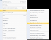
Ok I'm going crazy xD...
I get to this point then i don't know how to export the data, I've spent 3 hours without figuring out the problem, I'm sure is a stupid thing and you can help me.
The airport in the 1x1 data is cut out this is why I have the 2x2 loaded.
FILENAME=
DESCRIPTION=DSM FIRST LiDAR con risoluzione a terra 2 metri - Regione Calabria (Terrain res of 2m)
UPPER LEFT X=15.6000000000
UPPER LEFT Y=40.1600000000
LOWER RIGHT X=17.3000000000
LOWER RIGHT Y=37.8800000000
WEST LONGITUDE=15° 36' 00.0000" E
NORTH LATITUDE=40° 09' 36.0000" N
EAST LONGITUDE=17° 18' 00.0000" E
SOUTH LATITUDE=37° 52' 48.0000" N
UL CORNER LONGITUDE=15° 36' 00.0000" E
UL CORNER LATITUDE=40° 09' 36.0000" N
UR CORNER LONGITUDE=17° 18' 00.0000" E
UR CORNER LATITUDE=40° 09' 36.0000" N
LR CORNER LONGITUDE=17° 18' 00.0000" E
LR CORNER LATITUDE=37° 52' 48.0000" N
LL CORNER LONGITUDE=15° 36' 00.0000" E
LL CORNER LATITUDE=37° 52' 48.0000" N
PROJ_DESC=Geographic (Latitude/Longitude) / WGS84 / arc degrees
PROJ_DATUM=WGS84
PROJ_UNITS=arc degrees
EPSG_CODE=EPSG:4326
COVERED AREA=37261 sq km
NUM BANDS=4
PIXEL WIDTH=0.0000987 arc degrees
PIXEL HEIGHT=0.0000987 arc degrees
BIT DEPTH=24
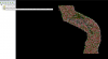
I manage to isolate the data to only lidar ground vertex I guess?
FILENAME=
DESCRIPTION=
AREA COUNT=197313
AREA VERTEX COUNT=870967
LINE COUNT=0
POINT COUNT=0
MESH COUNT=0
UPPER LEFT X=3325840.044
UPPER LEFT Y=249721.179
LOWER RIGHT X=3328982.641
LOWER RIGHT Y=245738.425
WEST LONGITUDE=15° 37' 43.6106" E
NORTH LATITUDE=38° 05' 12.6468" N
EAST LONGITUDE=15° 40' 07.4657" E
SOUTH LATITUDE=38° 02' 54.9639" N
UL CORNER LONGITUDE=15° 38' 00.6259" E
UL CORNER LATITUDE=38° 05' 12.6468" N
UR CORNER LONGITUDE=15° 40' 07.4657" E
UR CORNER LATITUDE=38° 05' 02.0073" N
LR CORNER LONGITUDE=15° 39' 50.3784" E
LR CORNER LATITUDE=38° 02' 54.9639" N
LL CORNER LONGITUDE=15° 37' 43.6106" E
LL CORNER LATITUDE=38° 03' 05.5974" N
PROJ_DESC=Swiss Grid (LV95) / CH1903+ / meters
PROJ_DATUM=SWISS GRID (CH1903+)
PROJ_UNITS=meters
EPSG_CODE=EPSG:2056
BBOX AREA=12.516 sq km
I've put this on global mapper to download the map.
PS: The data from http://www.pcn.minambiente.it/viewer/ can't be downloaded, I have to send the email request to the ministry of the environment and wait 30 days.
Your task requires actual LiDAR elevation data identified via the Viewer portal and requested from M.O.E.
The WMS data only displays a graphic of a map of coverage extents assembled on the WMS GIS data applications, which is not actual elevation source data that could be used as a elevation data source.
This has been an increasing problem with the EU GIS data portals.
PS: Be sure to note the latter part of the [EDITED] info I linked to above:
Now I can write it with certainty, because I have tried it and I have had confirmation from several readers of the blog: the times for the delivery of data have been reduced .
And much !!!
To date, the Ministry fulfills a request in a few days!
If you are ready with pre-filled forms and paid postal order it is a matter of waiting just over 24 hours.
This is excellent news to which my personal applause goes to the ministerial service. Thanks!"
Perhaps we may see an updated status on your data from you in a few days ?
This site uses cookies to help personalise content, tailor your experience and to keep you logged in if you register.
By continuing to use this site, you are consenting to our use of cookies.


")
")