All right, a few things to keep in mind:
1.) The airfoil images are composites generated from several sources
2.) They seem to mirror reality fairly closely, but there can be no guarantees
The first image is the DC-9-10 airfoils and is a composite of figures from the maintenance manual and from a journal article that escapes me. The annotations are geared towards building 3D wing geometry and are mostly useless, but do indicate span percent and incidence (taken from the graph, may not be correct, as was pointed out, the graph is reporting the incidence of the zero lift line). Note that I drew a line from the apex of the airfoil to the trailing edge, and then rotated the images until this line was straight, so that I could build the geometry by the numbers. So consider these drawings to be at zero degrees incidence.

The second image is from the DC-9-10 maintenance manual. The red outline is the -30 leading edge. I superimposed a photo of an Aeromexico DC-9 of Playboy heritage that is now a static display. The wings were sliced just outboard of the fuselage, and the slats were not present. This exposed the flat spot on the wing body fairing where the slats cover up the leading edge. It was simply a matter of tracing the outline, and positioning it on the drawing until it fit (double checking with thickness to chord approximations based on photos and the like).

This is just the root... but the thing about MacDac's civil division, as much as I love 'em, is that they were perpetually short on cash and tended to resort to quick fixes (Proof? The DC-9-80: an airliner built to meet the needs of 1971, but delivered in 1979. Further proof? The "let's forget about the aerodynamic problem today and design a new fairing tomorrow" ideology). I have a hard time believing that the slat airfoil changes much beyond being squashed to fit the thinner wingtip while maintaining roughly the same chord. The 737s doesn't, and Boeing had money. So you could extrapolate the slat airfoil to the tip, squash it to fit, keeping in mind the proper locations of the slat edge, and it'll probably be close.
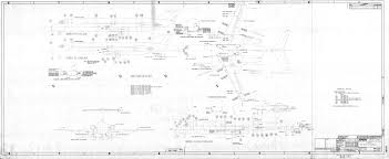
Here are some more Douglas diagrams I scoured off the almighty Google:
The above image was the starting point for my higher-resolution composite.
The original numbers were kind of hard to read, so I replaced them with more legible text.
Remember that the core wing is the same on all DC-9s, even the MD80 wing core is the same, just with a tip and root extension. So, you can compare this to a -10 station diagram and figure out fairly precisely where the -10 wing has to be modified to make a -30 wing (I say -30 because the correct way to count in DC-9-ish is 10, 31/32, 40, 20, 50, 33/34).
DC-9-10 wing stations:
DC-9-all vstab stations (don't trust the tailcone contours, the DC-9 cone points up a bit):
DC-9-all hstab stations (note that you get the vstab airfoil in this image and the hstab airfoil in the last one):
I am not totally certain how the raked wingtip fits on the -10... but it's not in any of the figures, so I think we can ignore it when building the core wing, and just consider it an aft skin extension (i.e. don't worry about how it fits into the tip airfoil).
So this should be enough to build either a -10 or -30 wing. I decided to go chronologically, so I built the -10 wing first, and, someday, if the model is ever finished, the -30 modifications will be done appropriately.


")