- Messages
- 2,192
- Country

Hello everyone.
I am the guy, who took over in 2009 the task of editing and updating the ADE Manual, which was written by Bob Keeshan some ADE-versions ago.
Many things have changed since then, necessitated by user requests and most of all by Jon Masterson's creativity

One of the areas of never ending discussions was - and still is - "layering", both in ADE and FS9/FSX.
The last and very significant contribution was offered by Jon himself in http://www.fsdeveloper.com/forum/showthread.php?t=426274&highlight=layers
I find myself now confronted with the task to incorporate all this wisdom into the Manual in a concise, precise, short, but still readable format.
I did my own research for this. And it turned out that the data are more suitable for a lengthy Tutorial, than for a condensed Manual in Bob Keeshan's style and tradition.
I therefore take the risk and present here all my findings, open for everyone, open for criticism, open for ridicule.
And I hope that you all do just all that.")
Please bear in mind that English is not my native tongue - don't hesitate to point out and correct all my Teutonic creations and aberrations.
Here we go")
-----------------------------------------------------------
The problem of "Layering" in airport design raises its ugly head when- and whereever airport elements overlap each other or have to be placed on top of each other.
The problem is made more complex, because layering is slightly different in ADE9 from FS9 and in ADEX from FSX and in some cases both ADE/FS-versions differ from each other - yes, it's quite a mess.
In ADE it is a question of visibility, in FS it is a question how the Simulator represents the results of the designers efforts, which not necesserily fulfill always the expectations .
.
The method for bringing order into that chaos is Machiavellian: create a hirarchy where each element has its place.
In FS the ACES generated a (not always) logical layer order, in ADE Jon Masterson allocates layer numbers to each airport element.
Jon's approach has the beauty that the numbers can - within limits - be changed, whereas the FS-system is frozen solid. Three cheers for the ACES.
The ugly head of layering is based on the fact, that airport elements are so very different from each other.
.... - ... in ADE they are all visible (of course), in FS some are invisible (NDB etc.).
.... - ...Some are three-dimensional, some are flat (two-dimensional)
.... - ...Of the flat objects, some are visible in FS (helipad, aprons etc.), some are not (navaids).
.... - ...Of the flat objects some change the airport terrain (vectors, Polygons)
That is why I differentiate in the following between the types of airport elements.
-----------------------------------------------------
Let's tackle the ADEX/FSX-situation first.
(1) RUNWAYS
No airport without runways

In the context of this discussion here, runways are the easiest problem.
First they rarely sit on top of each other in such a way, that they obstruct visibility (in ADE).
And second they have both in ADE and FS the same hirarchy, based on their surfaces.
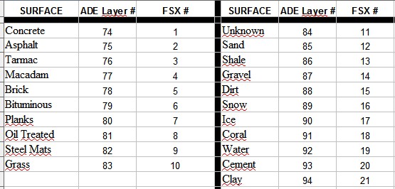
Figure 1: List of layer numbers for Runways
From this table it can be seen, that the surface "Concrete" in both ADEX and FSX is the top guy, whereas "Dirt" is pretty low on the totem pole.
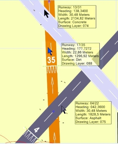

Figure 2: Runways in ADEX........................................................Figure 3: Runways in FSX
I think, these figures tell the story.
(2) TAXIPATH
Taxipaths are a difficult proposition, because they, together with taxi points, have more than one layer to make them work in the display:
Quoting Jon Masterson:
"There is a layer that shows the taxi point as a colored spot and one (lower) that shows the surface. There is a layer that shows the colored line representing the path (that can be selected etc) and a lower one that shows the surface. Points and lines are near the top of the pile when it comes to getting drawn; surfaces are lower down. Point surfaces need to overlay path surfaces otherwise the taxi network does not get drawn properly. Junction markings are in yet another layer. Messing these up would cause a lot of unexpected issues."
That is why taxipaths have just one fixed layer number, namely "5", which cannot be changed.
But then, how is layering done for Taxipaths?
In ADE it is simple: First In Last Out. The last Taxipath drawn is on top, the first one is the low guy. And you cannot change that. But that really does not matter, since Taxipaths are not supposed to sit on top of each other. That makes individual editing easy and feasable.

Figure 4: Taxipaths in ADE
In the example of the figure above, the "Tarmac"-taxipath was added first and the taxipath "Gravel" was the last, putting it on top of everything.
In FSX it is different.
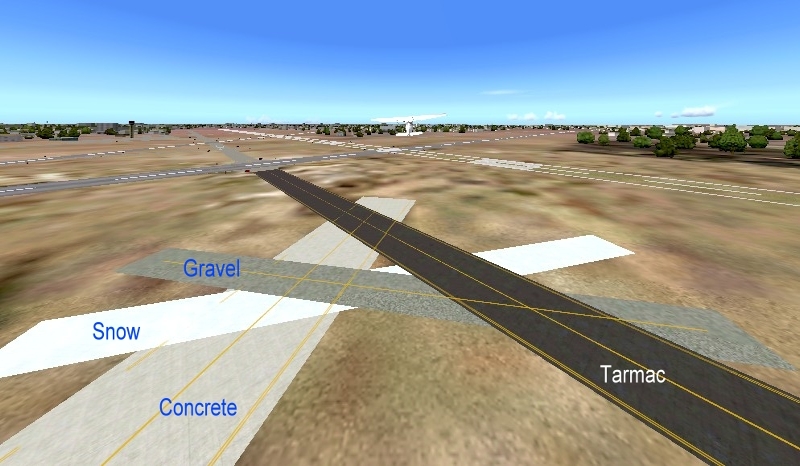
Figure 5: Taxipaths in FSX
Here the "Tarmac" is on top and "Concrete" is at the bottom, because
FSX uses for Taxipaths a layering hirarchy, which is listed in Fig. 6 below:

Figure 6: List of layer numbers in FSX for Taxipaths
(3) Aprons
For aprons the situation with layering is identical with Taxipaths (see above)
(4) AIRPORT Objects with a Range of Layers
The list of objects, which can be added to an airport and which can cause a problem when they sit on top of each other, is pretty long. (You can see them by using the "Context Menu" (right click) and there the option "Add".)
But there are much more.
For all of them Jon Masterson has introduced a clever layering system.
There are 150 drawing layers where 0 is the top (anything in 0 will be drawn over all other things). Each different object type or display element is assigned to a set of layers.
There are three numbers provided for each - a minimum layer, a maximum layer and a default layer (where something gets drawn when you create it).
For example: ............LibraryObject ...4,69,39
This means that a library object can be drawn in any layer from 4 thru 69 and when you create one it will be drawn in layer 39. Re-ordering a library object in the ADE display can be done between layers 4 and 69. Thus a library object cannot be drawn over something in layer 3 or below something in layer 70.
The following table contains all three values per airport objects.
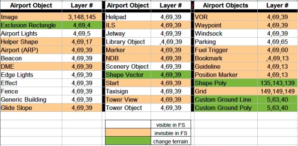
Figure 7: List of layer numbers for Objects
The main use of layering of airport objects is for the designers work in ADE.
In the ADE display objects frequently obscure each other.
A classical case is, where the "Tower Viewpoint" is placed on the same spot as the "Airport Reference Point" (ARP) and on top of this a "Tower" scenery object is placed.
In FSX this case does not pose a problem, because ARP and Tower Viewpoint are not displayed there.
But in ADE the actual tower building, having the biggest footprint, makes any access to the lower objects and their editing impossible.
This can be solved in many cases by using the options in the "View"-menu together with the "Hide Object"-option in the Context Menu.
But changing the layer of an obscuring object with the Context-menu-option "Move Back/Move To Back" or of an obscured object with "Move Forward/Move To Front" solves the problem in all individual cases.
To demonstrate this, in the next picture a hypotetical case was designed in ADE.
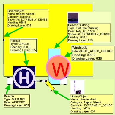
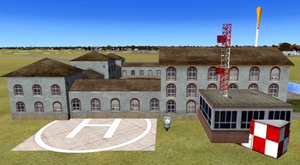
Figure 8: Layered Objects in ADE........................................ Figure 9: Layered Objects in FSX
There is not much to discuss here. Whatever is done in ADE, FSX simply displays the objects as in real life: "big covers small".
By the way, in Figure 9 there is a "lucky shot" showing, that Generic Buildings do not necessarily always sit smack on the ground. This one doesn't! But this is a different construction site and will not be discussed here
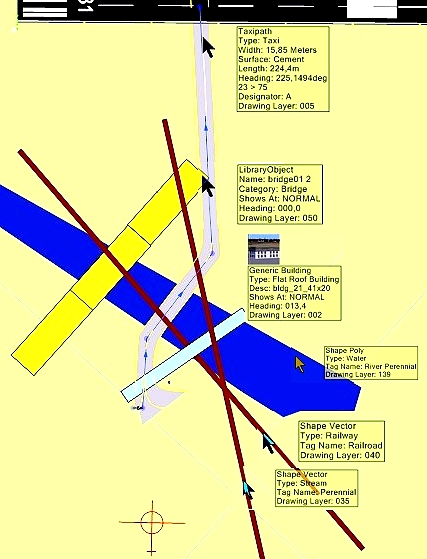
(5) Layering of Terrain Vectors (Shape Vectors)

will be continued
yours truely
Helli
I am the guy, who took over in 2009 the task of editing and updating the ADE Manual, which was written by Bob Keeshan some ADE-versions ago.
Many things have changed since then, necessitated by user requests and most of all by Jon Masterson's creativity
One of the areas of never ending discussions was - and still is - "layering", both in ADE and FS9/FSX.
The last and very significant contribution was offered by Jon himself in http://www.fsdeveloper.com/forum/showthread.php?t=426274&highlight=layers
I find myself now confronted with the task to incorporate all this wisdom into the Manual in a concise, precise, short, but still readable format.
I did my own research for this. And it turned out that the data are more suitable for a lengthy Tutorial, than for a condensed Manual in Bob Keeshan's style and tradition.
I therefore take the risk and present here all my findings, open for everyone, open for criticism, open for ridicule.
And I hope that you all do just all that.
Please bear in mind that English is not my native tongue - don't hesitate to point out and correct all my Teutonic creations and aberrations.
Here we go
-----------------------------------------------------------
The problem of "Layering" in airport design raises its ugly head when- and whereever airport elements overlap each other or have to be placed on top of each other.
The problem is made more complex, because layering is slightly different in ADE9 from FS9 and in ADEX from FSX and in some cases both ADE/FS-versions differ from each other - yes, it's quite a mess.
In ADE it is a question of visibility, in FS it is a question how the Simulator represents the results of the designers efforts, which not necesserily fulfill always the expectations
.The method for bringing order into that chaos is Machiavellian: create a hirarchy where each element has its place.
In FS the ACES generated a (not always) logical layer order, in ADE Jon Masterson allocates layer numbers to each airport element.
Jon's approach has the beauty that the numbers can - within limits - be changed, whereas the FS-system is frozen solid. Three cheers for the ACES.
The ugly head of layering is based on the fact, that airport elements are so very different from each other.
.... - ... in ADE they are all visible (of course), in FS some are invisible (NDB etc.).
.... - ...Some are three-dimensional, some are flat (two-dimensional)
.... - ...Of the flat objects, some are visible in FS (helipad, aprons etc.), some are not (navaids).
.... - ...Of the flat objects some change the airport terrain (vectors, Polygons)
That is why I differentiate in the following between the types of airport elements.
-----------------------------------------------------
Let's tackle the ADEX/FSX-situation first.
(1) RUNWAYS
No airport without runways
In the context of this discussion here, runways are the easiest problem.
First they rarely sit on top of each other in such a way, that they obstruct visibility (in ADE).
And second they have both in ADE and FS the same hirarchy, based on their surfaces.
Figure 1: List of layer numbers for Runways
From this table it can be seen, that the surface "Concrete" in both ADEX and FSX is the top guy, whereas "Dirt" is pretty low on the totem pole.
Figure 2: Runways in ADEX........................................................Figure 3: Runways in FSX
I think, these figures tell the story.
(2) TAXIPATH
Taxipaths are a difficult proposition, because they, together with taxi points, have more than one layer to make them work in the display:
Quoting Jon Masterson:
"There is a layer that shows the taxi point as a colored spot and one (lower) that shows the surface. There is a layer that shows the colored line representing the path (that can be selected etc) and a lower one that shows the surface. Points and lines are near the top of the pile when it comes to getting drawn; surfaces are lower down. Point surfaces need to overlay path surfaces otherwise the taxi network does not get drawn properly. Junction markings are in yet another layer. Messing these up would cause a lot of unexpected issues."
That is why taxipaths have just one fixed layer number, namely "5", which cannot be changed.
But then, how is layering done for Taxipaths?
In ADE it is simple: First In Last Out. The last Taxipath drawn is on top, the first one is the low guy. And you cannot change that. But that really does not matter, since Taxipaths are not supposed to sit on top of each other. That makes individual editing easy and feasable.
Figure 4: Taxipaths in ADE
In the example of the figure above, the "Tarmac"-taxipath was added first and the taxipath "Gravel" was the last, putting it on top of everything.
In FSX it is different.
Figure 5: Taxipaths in FSX
Here the "Tarmac" is on top and "Concrete" is at the bottom, because
FSX uses for Taxipaths a layering hirarchy, which is listed in Fig. 6 below:
Figure 6: List of layer numbers in FSX for Taxipaths
(3) Aprons
For aprons the situation with layering is identical with Taxipaths (see above)
(4) AIRPORT Objects with a Range of Layers
The list of objects, which can be added to an airport and which can cause a problem when they sit on top of each other, is pretty long. (You can see them by using the "Context Menu" (right click) and there the option "Add".)
But there are much more.
For all of them Jon Masterson has introduced a clever layering system.
There are 150 drawing layers where 0 is the top (anything in 0 will be drawn over all other things). Each different object type or display element is assigned to a set of layers.
There are three numbers provided for each - a minimum layer, a maximum layer and a default layer (where something gets drawn when you create it).
For example: ............LibraryObject ...4,69,39
This means that a library object can be drawn in any layer from 4 thru 69 and when you create one it will be drawn in layer 39. Re-ordering a library object in the ADE display can be done between layers 4 and 69. Thus a library object cannot be drawn over something in layer 3 or below something in layer 70.
The following table contains all three values per airport objects.
Figure 7: List of layer numbers for Objects
The main use of layering of airport objects is for the designers work in ADE.
In the ADE display objects frequently obscure each other.
A classical case is, where the "Tower Viewpoint" is placed on the same spot as the "Airport Reference Point" (ARP) and on top of this a "Tower" scenery object is placed.
In FSX this case does not pose a problem, because ARP and Tower Viewpoint are not displayed there.
But in ADE the actual tower building, having the biggest footprint, makes any access to the lower objects and their editing impossible.
This can be solved in many cases by using the options in the "View"-menu together with the "Hide Object"-option in the Context Menu.
But changing the layer of an obscuring object with the Context-menu-option "Move Back/Move To Back" or of an obscured object with "Move Forward/Move To Front" solves the problem in all individual cases.
To demonstrate this, in the next picture a hypotetical case was designed in ADE.
Figure 8: Layered Objects in ADE........................................ Figure 9: Layered Objects in FSX
There is not much to discuss here. Whatever is done in ADE, FSX simply displays the objects as in real life: "big covers small".
By the way, in Figure 9 there is a "lucky shot" showing, that Generic Buildings do not necessarily always sit smack on the ground. This one doesn't! But this is a different construction site and will not be discussed here
(5) Layering of Terrain Vectors (Shape Vectors)
will be continued
yours truely
Helli
Last edited:


