-
Which the release of FS2020 we see an explosition of activity on the forun and of course we are very happy to see this. But having all questions about FS2020 in one forum becomes a bit messy. So therefore we would like to ask you all to use the following guidelines when posting your questions:
- Tag FS2020 specific questions with the MSFS2020 tag.
- Questions about making 3D assets can be posted in the 3D asset design forum. Either post them in the subforum of the modelling tool you use or in the general forum if they are general.
- Questions about aircraft design can be posted in the Aircraft design forum
- Questions about airport design can be posted in the FS2020 airport design forum. Once airport development tools have been updated for FS2020 you can post tool speciifc questions in the subforums of those tools as well of course.
- Questions about terrain design can be posted in the FS2020 terrain design forum.
- Questions about SimConnect can be posted in the SimConnect forum.
Any other question that is not specific to an aspect of development or tool can be posted in the General chat forum.
By following these guidelines we make sure that the forums remain easy to read for everybody and also that the right people can find your post to answer it.
You are using an out of date browser. It may not display this or other websites correctly.
You should upgrade or use an alternative browser.
You should upgrade or use an alternative browser.
P3D v2 T-346A
- Thread starter SixGhost
- Start date

 Good were the days when I only modeled WW2 stuff!
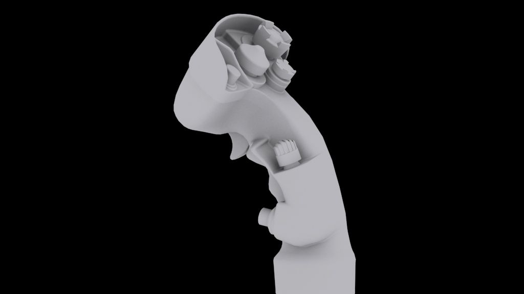


Paul Domingue
Resource contributor
- Messages
- 1,532
- Country

Thanks pal!
In between a whole lot of preparatory research work and boring splines, modelling of the lateral consolles has started.
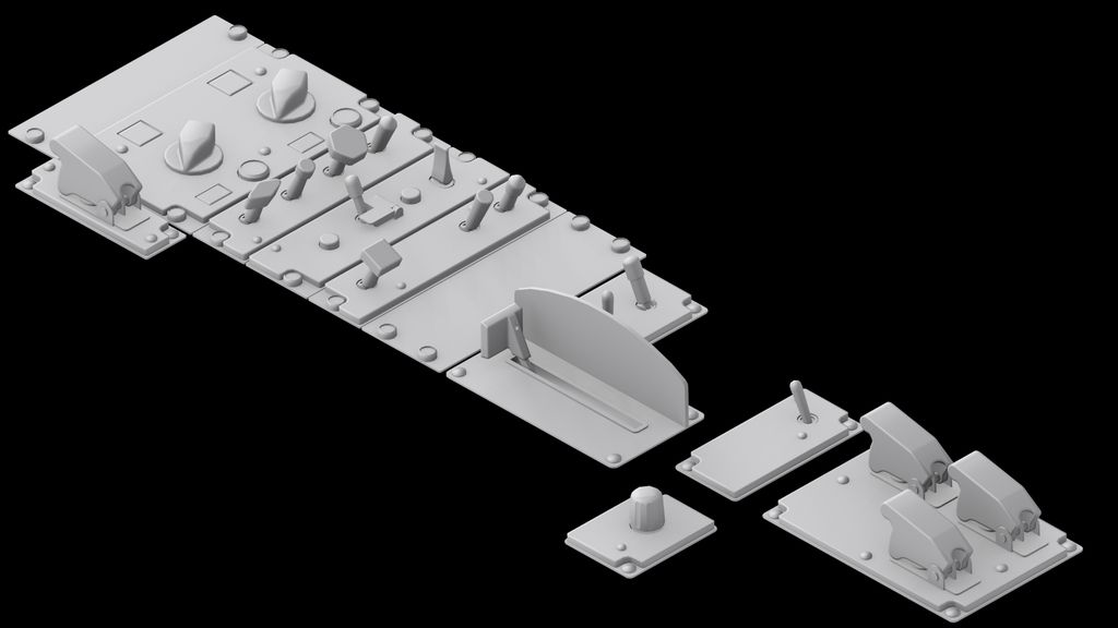
Nice stuff, so clean and crisp. I would like to see the same image in wire frame mode if you don't mind sir.
SixGhost
Resource contributor
- Messages
- 103
- Country

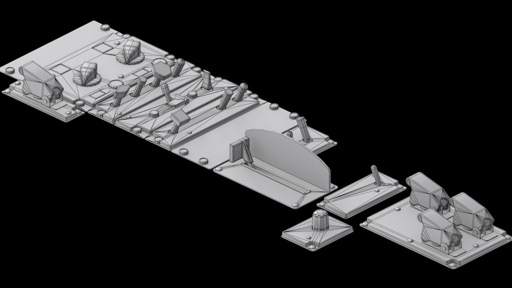
Sure Paul, as you can see, the least amount of geometry needed to confine the creases where I want them. It's all done through insets and manual "connection" of the resulting edges when they create a corner. Faces are mostly perpendicular, eliminating the use of poly-heavy and irritating sub 1mm chamfers on small parts while cramping detail. Hope it's clear, I can explain it further through examples if there's any interest. (you might want to see the image at full res, the forum resized it)
Paul Domingue
Resource contributor
- Messages
- 1,532
- Country
Thanks for posting. I wanted to see how you handled the toggle insets to prevent irregular surface normals.Sure Paul, as you can see, the least amount of geometry needed to confine the creases where I want them. It's all done through insets and manual "connection" of the resulting edges when they create a corner. Faces are mostly perpendicular, eliminating the use of poly-heavy and irritating sub 1mm chamfers on small parts while cramping detail. Hope it's clear, I can explain it further through examples if there's any interest. (you might want to see the image at full res, the forum resized it)
- Messages
- 112
- Country

Wow. Great work. Would definitely love to see more examples especially on the technique you were explaining please. Thank you in advance.
jtanabodee
Resource contributor
- Messages
- 3,924
- Country

Fantastic work!
SixGhost
Resource contributor
- Messages
- 103
- Country
This is an example to explain the basics, we'll use simple cubes, how original!
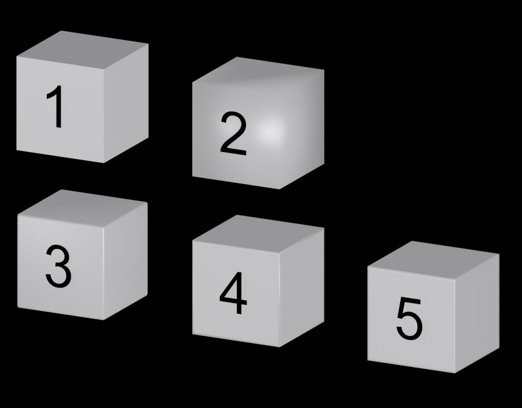
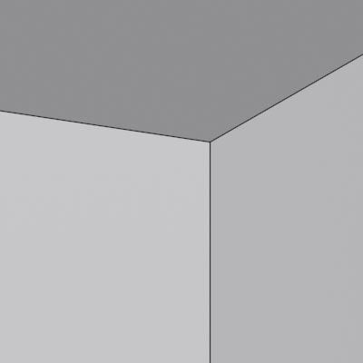
1 is a cube with hard edges, a different smoothing group for each face, your normal bare bones mesh. 12 tris, 6 smoothing groups. See below:
2 is the same mesh with a single smoothing group applied, notice how the light is distorted, you are graphically trying to round something that isn't. When in motion, your cube will look even more like crap. 12 tris, 1 smoothing group. No image because you should avoid doing that, fullstop.
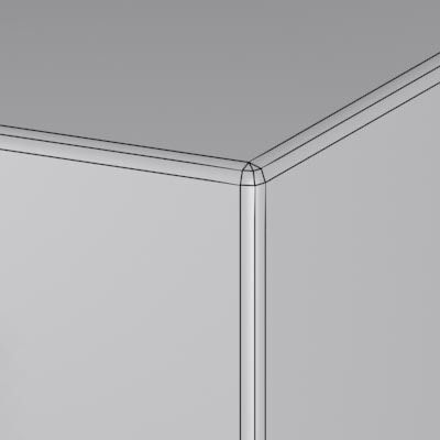
3 is a cube with its edges chamfered two times, it looks nice and the edges are effectively round now, you should be a bit more careful when texturing since you'll have distortions when planar mapping and the corners will result in a headache if you want to minimize seams in the textures. The faces look good but the program is still trying to evenly distribute a curvature between the edge poligons and the planar faces. (can be barely seen in the image) To alleviate that, you should add more iterations (and polys) to your initial chamfer. It's very hard to control our dear 1mm threshold when doing tiny pieces. 108 tris, 1 smoothing group.
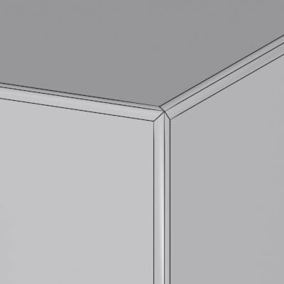
4 is a cube with all its faces inset by a small amount. Notice how the light is not evenly bouncing on the edges. All the faces are still perpendicular to each other, but even if the program is trying to reach an approximation between each face, the creases generated over the corners "bleed" through the edges. It's easier to map but when in motion it doesn't look good. To be avoided. 60 tris, 1 smoothing group.
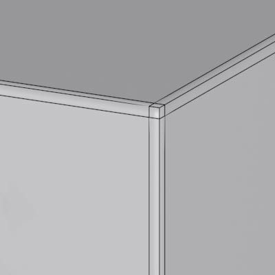
5 is the same cube from number 4 but its creases have been confined by connecting the edges over the corners. It looks good, even in motion, it's easier to map and to texture since every face is perpendicular. It takes a little bit of time for overcomplicated or tiny meshes, but the results are stunning considering that in reality you still have a cube with hard edges. You can easily control the 1mm threshold by setting a fixed distance when you inset. 108 tris, 1 smoothing group.
1 is a cube with hard edges, a different smoothing group for each face, your normal bare bones mesh. 12 tris, 6 smoothing groups. See below:
2 is the same mesh with a single smoothing group applied, notice how the light is distorted, you are graphically trying to round something that isn't. When in motion, your cube will look even more like crap. 12 tris, 1 smoothing group. No image because you should avoid doing that, fullstop.
3 is a cube with its edges chamfered two times, it looks nice and the edges are effectively round now, you should be a bit more careful when texturing since you'll have distortions when planar mapping and the corners will result in a headache if you want to minimize seams in the textures. The faces look good but the program is still trying to evenly distribute a curvature between the edge poligons and the planar faces. (can be barely seen in the image) To alleviate that, you should add more iterations (and polys) to your initial chamfer. It's very hard to control our dear 1mm threshold when doing tiny pieces. 108 tris, 1 smoothing group.
4 is a cube with all its faces inset by a small amount. Notice how the light is not evenly bouncing on the edges. All the faces are still perpendicular to each other, but even if the program is trying to reach an approximation between each face, the creases generated over the corners "bleed" through the edges. It's easier to map but when in motion it doesn't look good. To be avoided. 60 tris, 1 smoothing group.
5 is the same cube from number 4 but its creases have been confined by connecting the edges over the corners. It looks good, even in motion, it's easier to map and to texture since every face is perpendicular. It takes a little bit of time for overcomplicated or tiny meshes, but the results are stunning considering that in reality you still have a cube with hard edges. You can easily control the 1mm threshold by setting a fixed distance when you inset. 108 tris, 1 smoothing group.
Dutcheeseblend
Resource contributor
- Messages
- 1,541
- Country

Thanks for this one, Luca! I translated this into Blender, since we have a slightly difference with respect to smoothing groups. Works exactly the same.
Never thought of faking rounded corners by not using rounded corners at all!
Never thought of faking rounded corners by not using rounded corners at all!
- Messages
- 588
- Country

Go easy with it mate, it's addictive! In no time you'll be using it on overy piece of mesh, I know I do!
Yep, you can quadruple Polycount in no time with this method. I go for Inset Faces (N° 4). Use sparingly, like for control surfaces, trailing edges, etc.
Cheers
")
- Messages
- 167
- Country
I'm just wondering, what is the treshold of 1mm? Is it the minimum thickness an object needs for FSX?
Nice modeling btw!
Cheers, Daniël
Nice modeling btw!
Cheers, Daniël