• Which the release of FS2020 we see an explosition of activity on the forun and of course we are very happy to see this. But having all questions about FS2020 in one forum becomes a bit messy. So therefore we would like to ask you all to use the following guidelines when posting your questions:

    • Tag FS2020 specific questions with the MSFS2020 tag.
    • Questions about making 3D assets can be posted in the 3D asset design forum. Either post them in the subforum of the modelling tool you use or in the general forum if they are general.
    • Questions about aircraft design can be posted in the Aircraft design forum
    • Questions about airport design can be posted in the FS2020 airport design forum. Once airport development tools have been updated for FS2020 you can post tool speciifc questions in the subforums of those tools as well of course.
    • Questions about terrain design can be posted in the FS2020 terrain design forum.
    • Questions about SimConnect can be posted in the SimConnect forum.

    Any other question that is not specific to an aspect of development or tool can be posted in the General chat forum.

    By following these guidelines we make sure that the forums remain easy to read for everybody and also that the right people can find your post to answer it.

MSFS Critical problem with normal maps in MSFS (Blender workflow)

Messages
233
Country
canada
There is something very wrong with NORMAL textures in MSFS while exporting Blender models (or with me, doing it wrong). I have finally nailed down the consistent problem I had with different-looking parts of my models with one and the same baked material. As soon as I disconnect normal MSFS material node everything looks just great (but flat of course, no lighting changes. no "bump" texture appearance). Please advise how to overcome this! It happens in most or all my models and it's very visible on corrugated metal materials because of their very prominent striped normal map.
Here is how the model appears in MSFS - look at the difference between the main wall part and top part just under the roof. Those are different faces, but baked normal texture image matches perfectly (I checked) and looks seamless adn all the same color in Blender.
1604093205770.png

Same happens on the side (thin stripe) and back with the hangar door etc. - different faces look different color. When I move the sun around, lighting changes differently on them. But as soon as I cut the node connection between normal map image and normal input and re-export, the problem disappears, but of course the wall is flat now. You can see that texture on those faces matches perfectly, and they were baked one right after another (diffuse and normal).
1604093227841.png

This is how it SHOULD look, but of course it should not be flat.
This is what I cut (see screenshot below). You can also see a part of the baked normal image. Believe me it matches fine. I have not edited anything after baking and assigning a new "baked" material as "MSFS Standard" and loading two baked images to diffuse and normal slots. That's allI did. The node map below is the automatic result from assigning MSFS material. I did not use any composite maps for metallic, roughness etc. - just set fixed valies via sliders.
1604093234676.png

Any help or ideas on what to try veru much appreciated. My airport is ready, but this is holding me off... I posted this as a separate topic from Blender2MSFS one, because this may be actually related to MSFS itself, or to Blender bug. And if not a fix, a workaround would be great. I don't know what else to try...
 
Last edited:
Messages
233
Country
canada
I was digging up texture files from other add-on airports (Asobo and Orbx) and their Normal texture files look nothing like mine. No wonder I'm having problems. So what am I doing wrong?
Here is a cmall chunk of a typical Normal file from Orbx airport (or Asobo - they all look the same):
1604092963869.png

They are all red and green mostly, with some yellow, and black empty areas, and it looks like channels are all different, and this is not revolving around a common bumps, like what's generated by Photoshop or by Substance Painter. And this is not a "composite" texture, definitely a "Normal". My files, generated in Blender by baking, all look like this:
1604092957935.png

They are all purple, with shades of purple and cyan offset in specific directions. All my Normal textures are like this. They are nothing like others. I tried reversing the green channel like someone mentioned, but it didn't help, and also it didn't change the look much - just black empty areas became green. So this all hints to me somehow not getting the Normal textures right. What am I doing wrong and what would be the right workflow for Blender?

Here is another example of a proper Normal file CHARLES_DE_GAULLE_02_NORMAL.PNG.DDS - again, nothing like mine. All green and red and they are completely independent of each other.
1604093461881.png
1604093612195.png

In a corresponding piece of an Albedo texture you cen seee that green designate Normal structure, some ridged bumps, while red is something else entirely. It's nothing like a normal Normal texture, which revolves around same features in all channels. Can anyone please solve this puzzle for me?
 
Last edited:
Messages
233
Country
canada
Based on the hunch that just green channel works like Normal map, I deleted other channels and reloaded it in Blender to export to MSFS. Now, it did not fix the problem in MSFS, but in Blender the hangar sudennly looked the same weird way as in MSFS! It means that whatever is happening in MSFS it only gets a single channel, or not all channels of a Normal map. Because with missing RGB channels the look in Blender is exactly the same! It means MSFS is NOT reading the purple normal map correctly. Something else has to be done! Now, how can I figure out what???
1604101549362.png
 
Messages
204
Country
us-texas
I looked in my global\scenery\TEXTURE directory for the actual .DDS normals. One of my normals was somehow converted by FS 2020 to the Yellow/Green/Red channels you see by others, but yet another in the DDS remained only purple. Best guess, there is a bug where the normal is failing to compile and it is just converting it to a standard DDS file keeping the color channels the same, when in reality I guess it needs to convert the channels?

It is probably related to the image format, maybe when you save it in the wrong bit depth it cannot convert it correctly (no idea, but I'll check it).

I am using Irfanview to view the DDS.
 
Last edited:
Messages
204
Country
us-texas
So on one of my normals that stayed purple as the .DDS, it does appear to be working correctly in the game. Hence, it looks like I wanted as far as the normal acting sort of like a height/bump map. It gave my roof the ridges and extra perceived bump I wanted, but it could just be that I got lucky and that it just came out that way, and that it was supposed to be converted to the Yellow/Green/Red (no idea).

I'd also be interested if someone has an explanation for this.
 
Messages
58
Country
germany
I meanwhile think that it is a bug. It wouldn't be the only one; default MSFS sceneries' towers do not have transparent windows ... why?
 

Pyscen

Resource contributor
Messages
2,993
Country
us-texas
What is the bit color (8 or 16) on the defaults and what are yours before and after?
 
Messages
210
Country
germany
Read about the problems. My opinion:

1. Do not care about other developers. You do not know what they are doing.
2. Open the sample materials in the FS SDK and you will find this:
-> Normals are blue
-> the map for occlusion, roughtness and metalic is the yellow red green one.

The reason for different colors are easy to find out, open the sample maps with Gimp and look at the color channels:

Normal map is RGB map with all channels are used for the normal
Occlusion/Roughness/Metalic map is a RGB + Alpa= RGBA. If developers only use the roughness, for exampe for windows, they only use the green channel. So they copy a greyscale of the roughness into this channel. This will look yellow, green, red.

You coud also read in the materials and texture section of the SDK about this.

Now your problem. If you see your model in wireframe mode in blender, maybe there are 2 faces of the area and one face is not flipped outside. Or there is a second face above in the area directly under the roof, which is darker. You could find out in UV-Editor.
 
Messages
233
Country
canada
Thanks for the info. This airport is released and the problem is (kinda) solved, but there is definitely a strange bug around that issue. The way I solved it is by ROTATING the offending shiny faces' UV maps 90 or 180 degrees. Normals were OK, no flipping was needed. But by just rotating the UB map for the face 180 degrees, or sometimes 90 degrees where it worked, made this issue disappear. I have no idea what caused this, and it definitely should not happen this way. I'm not sure which step has this bug: Blender, Blender2MSFS exporter, or MSFS. Most likely - MSFS. So the summary is for whoever faces this problem (faces! ha-ha) - the solution is rotating UV map for the offending faces until you don't see the problem anymore. For directional textures like corrugated metal or asymmetrical tiles - 180 degrees worked for me.

There seem to be another bug, maybe related. Normals behave incorrectly in MSFS, at least sometimes. On some angles of sun light on my materials they seem to cast shadows and look 3D in the right way, but the same material with a different lighting angle seems to "flip" inside-out and ridges become indents etc. - as if normals were flipped. I'm inverting Green channel as it's supposed to be inverted, but I tried without it and the result is the same. Some lighing casts correct shadows/reflections, other - inverted.
 
Messages
9
Country
canada
I'm having a similar time finding out about normal maps. In this case the problem RomanDesign is having is an geometry/UV issue. But he did observe similar things about normal maps to what I have. Some look very different than others when reading the .dds files back into standard image data in Gimp, Photoshop, Nvidia Texture tools. Almost every tool I find saves out the "purple style" normal maps. But many of the maps I'm finding are this "red and green style." I have to guess there's some settings, flags set in the PBR material definitions specifying what format to expect the associated maps to be written/read in. The issue for me is I'm trying to modify and improve some maps on someone else's aircraft and they are these "Red and green" looking maps. I can't find anything that will write them like that? But I'm also beginning to suspect that these maps may be written with a negative/positive bit. Because the unperturbed areas are black in the "red green" style. and the pixels on either side of a bumped or grooved feature in the map are both red in X and green in Y, at least once read into Gimp, Photoshop or Nvidia Texture tools. However the "purple style seems to have all positive values. Unperturbed areas are a middle color, I'd expect 127 in an 8 bit integer format, but that's not exactly what I'm seeing. But they do make logical sense, more than the red/green style, the purple maps have darker values on one side of a bump/groove, and lighter values on the other side, indicating the normals are bent in opposite directions with the purple style maps. The blue channel in the purple style maps seems to be solid color in some instances, and has a more bump or height like data in others? Like the bump/height maps that are used to generate the normals map to begin with.

My problem is for my current project I NEED to write them in the style they are written in the package I am trying to modify.

You make some good points Peter, but I don't think this is as clear as you make it out. And your answers are inconsistent. There's no way to write a normal map with one channel (blue as you suggest). A normal will at least need two axis, if you assume the third is tangent to the surface. Three if not. One channel can be used as a bump/displacement/height map, but then whatever is using the maps has to do the normal and/or point translations on the fly. This is what traditional CPU software renderers do, but for real time hardware accelerated uses that's too expensive, a pre baked multiple channel map is needed. And .dds is also made to take advantage of compression options the hardware supports as well for GPU memory savings.

"2. Open the sample materials in the FS SDK and you will find this:
-> Normals are blue"
And yet?

"The reason for different colors are easy to find out, open the sample maps with Gimp and look at the color channels:
Normal map is RGB map with all channels are used for the normal"

I've looked in the SDK docs and if it's there I missed any definitive description of the way or ways a normal map can be written for use in MSFS. Please point out what I'm missing!
 
Messages
39
Country
germany
You missed nothing, Dylaner.

Software Developer generally hate the creation of user guides profoundly. The MSFS-SDK manual is an impressive example.

The result will be shown in this forum. No central theme. Different good developers, different problems, but the same goal: Making a good scenery an be the best. In that way the scenery design becomes more complicated and some users think too much complex, too special and too much state of the art. It´s nearly impossible to identify a consistent and simple workflow for the different MSFS development categorys. My offer in that case: Think much easier, spend more time for your texture artwork and find your own way. Don´t be afraid about the professionals they only respond with wise suggestions. You´ll never know until you try - it pays off.

Using a normal mapping tool is helpful but it gives not the desired result in most instances. But it gives the colours you need for normal mapping. The normal maps in my project are partial hand painted (on pixel grid) to create sharp edges and removing unwanted (unrealistic) normal mapping results from any tool. I am using only four colors for the normal mapping effect on gaps and seams. Furthermore i try to avoid any color gradients created by the normal mapping tool. Simple - but effective:

NML_Map_clrs.jpg


It works, the result looks good so i did it my way (see attached file). No texture conversion or rendering trouble ingame. The normal scale scrollbar in Blender gives your a big space to setup the perfect normal map intensity without an ugly impact on other texture layers. For example the Occlusion, Roughness and Metallic map.

That map includes - for reflective model parts in my project - two colours only: YELLOW and RED. YELLOW = NO reflection (R: 255 G: 255 B: 0) RED=FULL reflection (R: 255 G: 0 B: 0). Reducing the opacity of RED texture parts above the YELLOW texture layer (Photoshop, Gimp whatever you´re using) gives less reflection. Simple - but effective. For metallic and glint effects on hangar wall surfaces (or other reflecting stuff) i am using a seperate Blender material definition. Without an Occlusion, Roughness or Metallic map. To create a material in Blender you have setup the Evee Render-Engine in the Blender-Render settings (Screen Space Reflections, Ambient Occlusion, egg). This is necessary to match the "what you see is what you get" experience during adjusting the material characteristics. Use the sliders on the right for adjusting the values, play with them and watch the result in realtime. Do not use the Blender shader editor. It looks impressive but it needs more working steps and keeps the danger of mistakes. This is scenery design only - and not a Pixar Animation Movie Production.

It´s enough already. PBR overacting at the airport environment (buildings, hangars, other bits and pieces) may lead to further problems and texture trouble. RomanDesign get that experience. In Germany we say: Keep the church in town. 🤪 
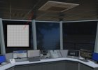
Much less can be much more. The attached example shows my texture workflow with hangar wall and goals parts. It works very well in MSFS. The inside view of the tower is one part of my own "overacting modeling" (sorry for that). Please keep attention to the ceiling only. In that case i had use black and white as a trial (not Yellow and Red) for reflection effects. It works similarly.
 

Attachments

  • Texture_example.jpg
    Texture_example.jpg
    1.5 MB · Views: 220
  • Texture_TWR_INT.jpg
    Texture_TWR_INT.jpg
    1.2 MB · Views: 256
Messages
233
Country
canada
Wow, and I thought my tower interior modeling might be excessively detailed, but your is absolutely crazy... BTW the normal map issues are virtually gone now, and I don't really know why. I try not tu rotate UVs unless necessary, and instead rotating 180 degrees I "flip Y". That seems to work it. On a very rare occasion I see the issue, I can rotate the UV map for the offending surface.

I do have another issue with ORM maps: sometimes when I copy-paste objects or append materials from another file, the roughness is not working at all. No reflections. Nothing seems to fix that unless I delete the material and create a new one and load diffuse/ORM/normal maps again from scratch. If I disconnect G channel from roughness in shated editor, and just use the slider - it works OK, but it doesn't want to work from the image. Happened several times. I can't fine the cause or a workaround.
1615619747274.png


1615619990526.png


1615620021709.png
 
Messages
39
Country
germany
Holy cow - i like that example of overmodeling so much. Very hard work. You only forgot binoculars, coffe cups with your signature and last but not least: The case for the controller´s contact lenses. :rotfl:
A tower (chase) view is strongly required in MSFS.
 
Messages
9
Country
canada
Well, Seems the issue was with the Nvidia Texture Tools. Opening the bump maps I was trying to improve in Paint.net they look like the grey-ish or purple maps that many bump map makers like the one in GIMP do. The red/yellow seems to be a mangled reading of the files as best as I can tell.
 
Messages
9
Country
canada
Does anyone know a way to look at the header or format of a .dds file to know exactly what type of .dds file and the options/flags used to make it?
 

Pyscen

Resource contributor
Messages
2,993
Country
us-texas
Hello

Normal maps are the same or universal. The only difference is after it has gone through the msfs compiler.

Normal maps are 16-bit png or tga format. They are then converted through the msfs compiler. This is unlike the other sims, where they are 8-bit, flipped vertically, and dxt5 dds format.
 
Messages
233
Country
canada
What I read recently is that the Blue channel is irrelevant for MSFS. I tried inverting the B channel (mostly black form mostly white) and got a similar look to those red/yellow images. No difference visible in the sim. So maybe MSFS just ignores blue channel and scenery developers didn't bothered with it? BTW I don't really see this initial problem with shimmering metallic faces anymore. It had definitely something to do with UV rotation. Maybe because I mostly use cube projection now, which doesn't randomly rotate UV faces for a better fit. When I had some, I could just flip or rotate the offending face and it made right.

One interesting case was when I used normal not generated by me - I always check inverted Y normal when exporting from Quixel Mixer. And the horizontal bars on windows looked inverted, like grooves. I went and inversed the Green channel of the normal image in Photoshop and the windows looked normal. So make sure that Y normal is inverted.

1616683443986.png
 
Messages
149
At the risk of repeating information that may be obvious to everyone, I thought I would try to explain what I have learned about normal maps and my understanding of how they are used in MSFS 2020 and Blender.

A normal map is an image file that stores information about the normal vectors at each visible point on a surface. The red channel in the image stores the X-axis component of the vector, and the green channel stores the Y-axis component. The blue channel stores the Z-axis component, but the normal maps used by MSFS assume a constant value of 255 for this component. So the normal map for a perfectly flat surface will have a uniform color of (128,128,255), which is the light purple color that you typically see in normal map files. The easiest way to visualize a normal map is to imagine a red light shining from the right side of the object, a green light shining from either above or below the object (more on this difference in a minute), and a blue light shining from directly in front of the object. See the following article for more:


Unfortunately, there are two competing approaches for encoding normal vectors in most video games: OpenGL and DirectX. OpenGL assumes that the green light is shining from above the object, which means that the Y-axis component starts counting from the bottom up, which is why this convention is sometimes called Y- Up. DirectX does the opposite. It assumes that the green light is shining from below the object, which means that the Y-axis component starts counting from the top down, which is why this convention is sometimes called Y+ Up. Here is a great illustration of these two conventions in use:

kf9jo.png


MSFS 2020 uses the DirectX convention for normal maps. So the normal map images that you use to texture your 3D objects should always been encoded for DirectX as if the green light is shining from below. If you have to switch a normal map image from OpenGL to DirectX, you need to invert the green channel in the image. You can do this in your image editor of choice. But my favorite way is to use this command in ImageMagick:

magick input.png -channel G -negate output.png

Unfortunately for anyone creating content for a game that uses DirectX, Blender renders normal maps using the the OpenGL convention. So a normal map encoded for DirectX will look wrong when displayed in Blender. I have discovered a good way to fix this, though. After you have created your MSFS-compliant material in Blender using the MSFS presets from the Blender2MSFS add-on, open your material in the Shading editor in Blender and insert these three nodes right before the purple "Normal Map" node:
  1. Separate the map into its X, Y, Z components.
  2. Subtract the Y component from 1.
  3. Combine the X, Y, Z components back into a new normal map
This is nicely illustrated here:


These three nodes invert the green channel, but only for display within Blender. It has no impact whatsoever on the export to MSFS. So you get to display the normals in Blender using the OpenGL convention, while still exporting the normals to MSFS using the DirectX convention. That way, the normals should appear the same in both Blender and MSFS. It would be great if these nodes could be added by default in a future revision to the Blender2MSFS add-on.

A final point on UV orientation. Because normal maps are used to indicate which direction a point on an object is facing, it is recommended that you keep your normal maps all oriented in a consistent direction when UV-mapping your object. So if you are using a single material to texture many faces of an object, I would recommend that as much as possible you try to orient the UV islands on the UV map so that the real-world "up" direction of each island points in the same direction on the UV map. For example, if you texture two sides of a building, but place one side on the UV map right-side up and the other up-side down, the color pattern may look the same, but the normals will be flipped and the light in game may cause the two sides of the building to look different.

Hope this sheds some light (pun fully intended) on this subject.
 
Top